


![]()
- Pianos / Synthesizers
- SYNTHESIZER
- Modular synths / sound modules
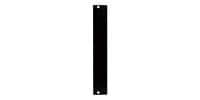
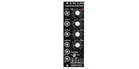
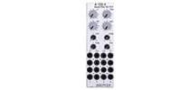
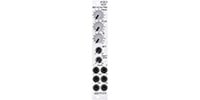
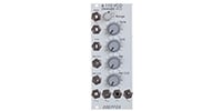
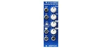
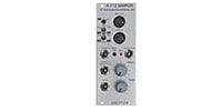
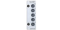
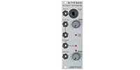
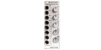
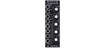
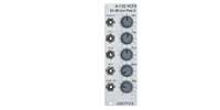
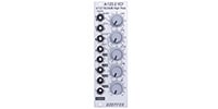
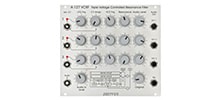
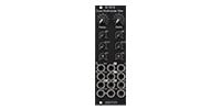
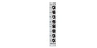
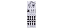
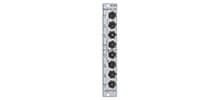
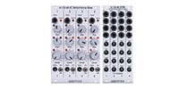
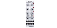
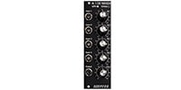
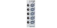
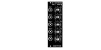
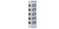
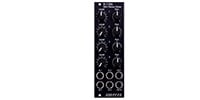
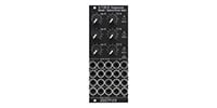
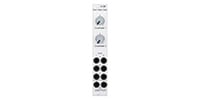
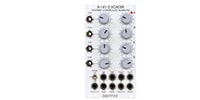
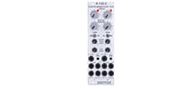
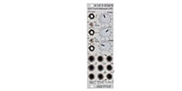
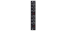
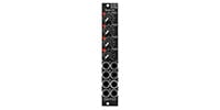
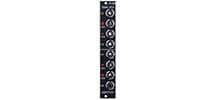
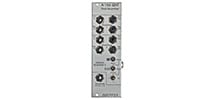
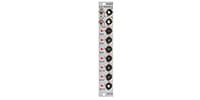
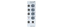
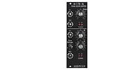
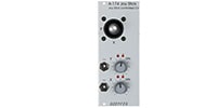
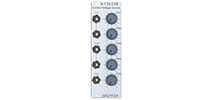
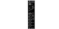
- DOEPFER/A-174-4 3D Joystick
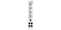
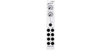
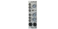
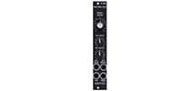
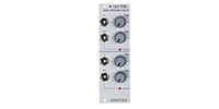
DOEPFER / A-174-4 3D Joystick


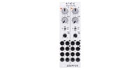
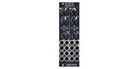
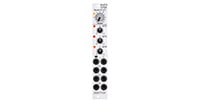
Variations


Back Order
Theremin Controller
Back Order
Dual Slew Limiter
Dual Slew Limiter
Back Order
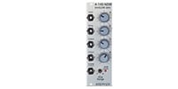
Slew Processor / Generator
Back Order
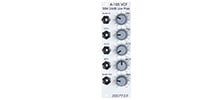
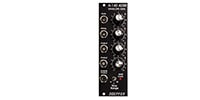
VC Slew Processor / Generator
Back Order
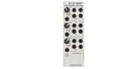
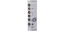
Max/Min Selector
Back Order
Transmitter / Receiver
Back Order
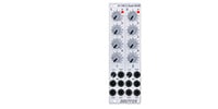
Joy Stick
Back Order
Wheels
Back Order
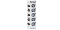
Dual Voltage Inverter
CV Source
Back Order
Ext Foot Controller 2
Special Order
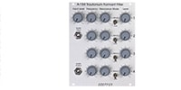
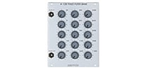
Quad VC Slew Limiter /

Special Order
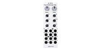
3D Joystick

Special Order
3D Joystick

Special Order
Theremin Voltage Source

Special Order
Light Controlled CV Source
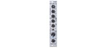
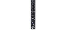
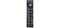


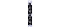
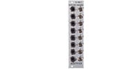
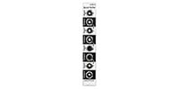
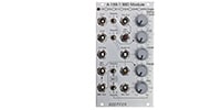
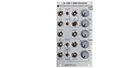


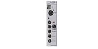
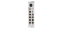
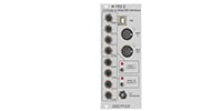

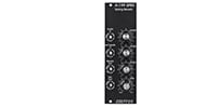

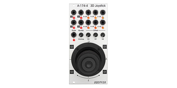
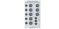
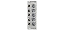
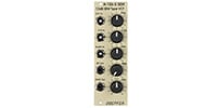
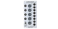
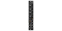
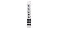
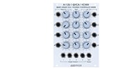
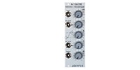
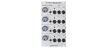
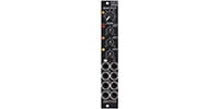
Normal (X+OX, Y+OY, Z+OZ) and inverted (-X+OX, -Y+OY, -Z+OZ) outputs with offset control
Normal (X+OX, Y+OY, Z+OZ) and inverted (-X+OX, -Y+OY, -Z+OZ) outputs are available for the joystick. The joystick outputs are bipolar, ranging from a normal CV of -5V (lowest position) through 0V (middle position) to +5V (highest position).
To this CV, three small offset control knobs OX, OY, and OZ can be used to add a variable voltage of up to 5V to the normal CV. The maximum offset control can be used to change the normal CV output range (-5V ~ 0V ~ +5V) to 0V ~ +10V. If the OX, OY, or OZ knob is turned fully counterclockwise, no offset voltage is added and “pure” CV is output; turning the OX, OY, or OZ knob clockwise will add up to 5 V of offset voltage to the normal voltage. V is added to the normal voltage when the OX, OY, or OZ knob is turned clockwise. Offset voltages are also added to the inverted outputs (-X, -Y, -Z), so setting the offset control to maximum will change the CV output range from normal (+5V ~ 0V ~ -5V) to +10V ~ 0V.
Dual color LEDs (red/yellow) are provided for each output to indicate the current voltage and to distinguish between positive (red) and negative (yellow) voltages.
Overlapable quadrant outputs (Q1, Q2, Q3, Q4)
An additional quadrant output (Q1, Q2, Q3, Q4) is provided to generate CV with a different algorithm than the six outputs. When the joystick is tilted toward one of the four quadrants separated by the X and Y lines of the joystick, a positive value of CV is output from the quadrant output corresponding to that direction. The Quadrant Overlap control allows the CVs between the quadrants to overlap. When the overlap is set to 0, CV is output only from the quadrant in the direction in which the joystick is currently tilted, while the other quadrant outputs remain at 0V. As the overlap control is increased, the voltages will gradually overlap. For example, as the overlap control is increased, CV is output from both Q1 and Q2 when the joystick is tilted toward 12 o'clock. Increasing the overlap control increases the amount of overlap. A single-color LED is provided for each quadrant output to indicate the current voltage. The quadrant outputs output only positive values of CV.
IMPORTANT NOTE
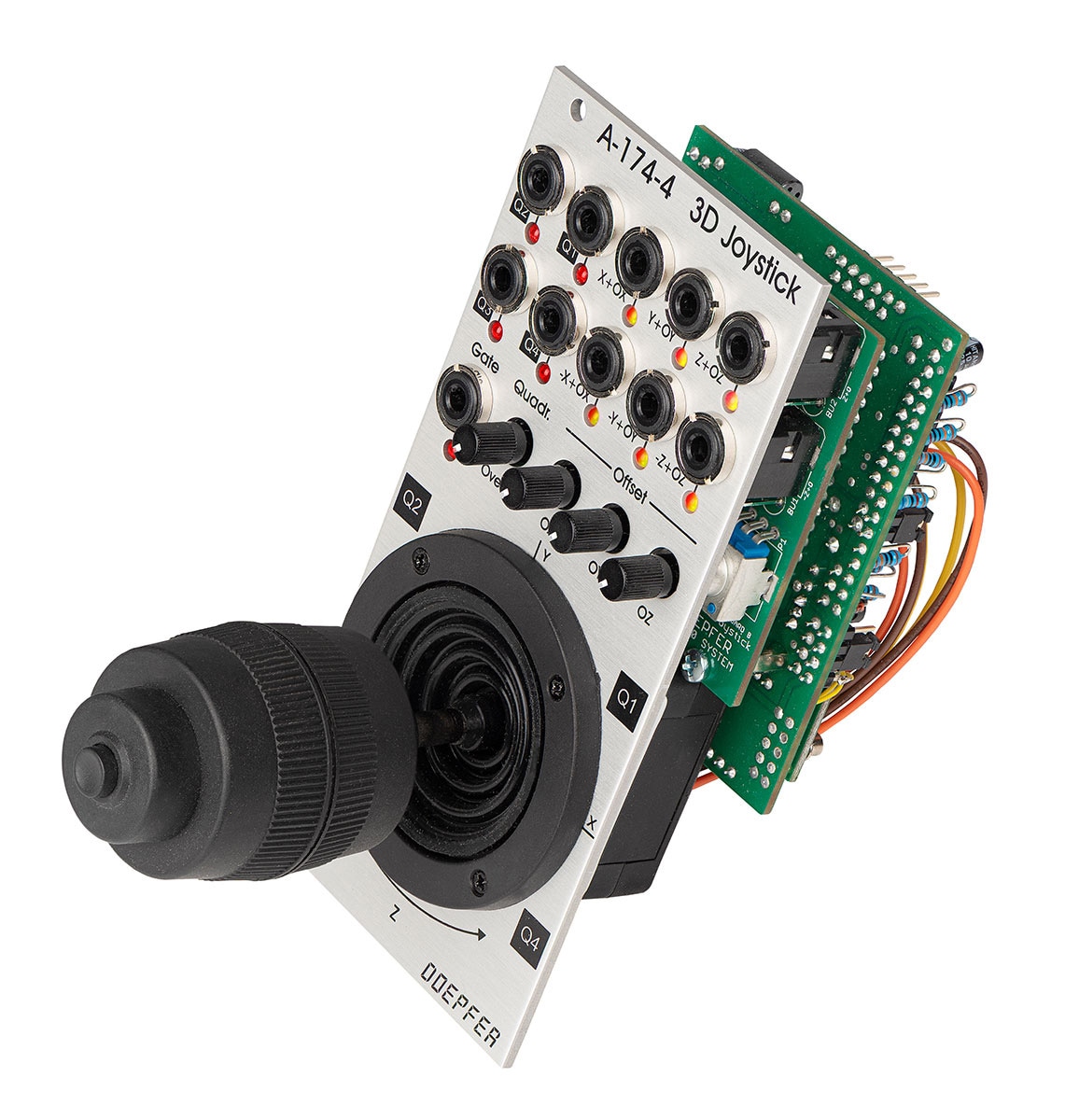
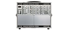
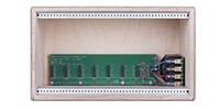
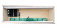
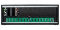
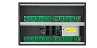
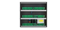
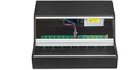
Because the joystick is 7 cm long from the panel to the tip, the lid cannot be closed when mounted in a portable case (A-100P6, A-100P9, A-100PMS6, A-100PMS9, A-100PMS12) that can be carried with a lid. It can be mounted on portable base cases (A-100PB, A-100PMB) and all cases without lids without any problem.
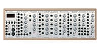
Width 12HP
Depth 50mm
Current consumption
+12V : 50mA
-12V : 20mA
関連商品
-
¥780(incl. tax)
 In Stock
 -
¥10,800(incl. tax)
In Stock -
¥34,800(incl. tax)
In Stock -
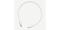
 KORG / SQ-CABLE-6 PATCH CABLE for SQ-1 ミニパッチケーブル
¥1,580(incl. tax)
In Stock -
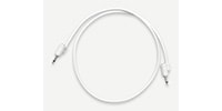
 MOOG / S.M CABLE 8 6/12/18/24IN Modular patch cable
¥4,950(incl. tax)
 Back Order
 -
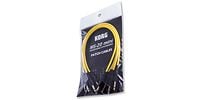
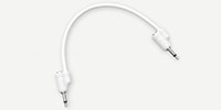 Tiptop Audio / Stackable Cable White 20cm x 5
¥5,698(incl. tax)
Back Order -
 Tiptop Audio / Stackable Cable White 30cm x 5
¥5,698(incl. tax)
 TBA
TBA -
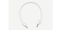
 Tiptop Audio / Stackable Cable White 50cm x 5
¥5,698(incl. tax)
TBA -
 Tiptop Audio / Stackable Cable White 70cm x 5
¥6,050(incl. tax)
Back Order -
 Tiptop Audio / Stackable Cable White 90cm x 5
¥6,050(incl. tax)
Back Order
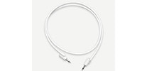
 KORG / MS-CABLE-YL
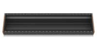 BEHRINGER / EURORACK 104
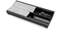 BEHRINGER / EURORACK GO
商品レビューProduct Review


不適切な投稿として報告しますか?
理由
ご協力ありがとうございました
投稿を削除しますか?
投稿されたレビューを削除しました。
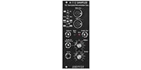
DOEPFER
A-174-4 3D Joystick
Item ID:369836
42,300 yen(incl. tax)
423Pt(1%)Detail
- 423Pts
通常ポイント
- 423Pts
Total
 Special Order
 - In Stock
- In Stock, can be shipped when order is confirmed.
- Low Stock
- Low Stock, may be sold out soon.
- Scheduled date
- Expected to arrive at Sound House on this date.
- TBA
- Expected date of arrival at Sound House to be determined.
- Back Order
- It needs to be orderd from the manufacturer. Please inquire about the estimated date of arrival.
- Mfr. Delivery
- Must be ordered from manufacturer. Please inquire about the estimated date of arrival.
- Download
- Only the serial number will be sent to your registered email address.
- Special Order
- Made to order item or must be ordered from manufacturer. May take several weeks or months.
- No Longer Available
- Product is no longer available due to having been discoutined or other reasons.
Rating

この商品に関連するセレクションRelated Articles
-
 Discount Sale
-
 Outlet
-
 New Arrivals
-
 Podcast (streaming)
-
 Headphones / Earphones
-
 Microphones
-
 Wireless Equipment
-
 Speakers
-
 Power Amps
-
 Mixers
-
 Processors
-
 Portable PA Systems
-
 Recorders
-
 Karaoke
-
 Guitars
-
 Basses
-
 Ukuleles
-
 Drums & Percussion
-
 Pianos / Synthesizers
-
 Wind Instruments
-
 Stringed Instruments
-
 Japanese Instruments
-
 Harmonicas, Other
-
 Software
-
 DJ & VJ
-
 Stands
-
 Cables & Connectors
-
 Racks & Cases
-
 Lighting
-
 Stage & Truss
-
 Video Equipment
-
 PC PERIPHERALS
-
 Power Supplies
-
 Studio Furniture
-
 Household Items, Other
-
 Alcoholic Beverages
Search by Brand
Brand List


- Sound House
- 〒286-0825 14-3 Shinizumi , Narita City, Chiba
- Monday-Friday 10:00-17:00
- Narita Call Center
- TEL. 0476-89-1111
- FAX. 0476-89-2222
- Tokushima Call Center
- TEL. 0885-38-1111
- FAX. 0885-38-1100
- Showroom Hours
- Monday-Friday 10:00-17:00
closed on Saturdays, Sundays and Holidays
© Sound House

すべてのレビューを見る