


![]()
- Pianos / Synthesizers
- SYNTHESIZER
- Modular synths / sound modules
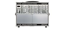
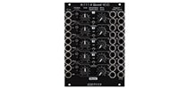
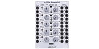
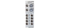
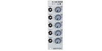
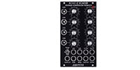
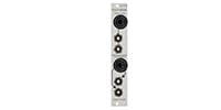
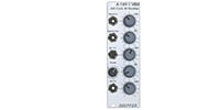
- DOEPFER/A-147-4V Dual VC LFO
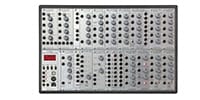
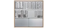
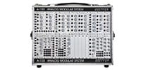
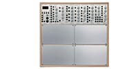
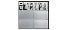
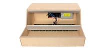
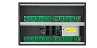
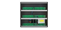
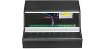
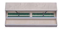
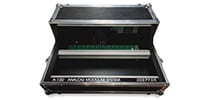
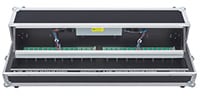
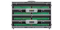
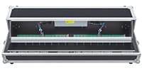
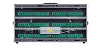
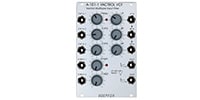
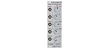
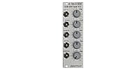
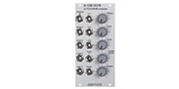
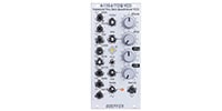
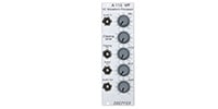
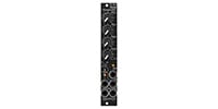
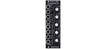
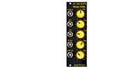
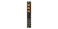
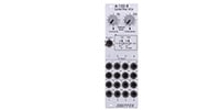
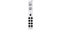
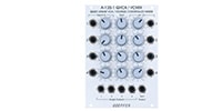
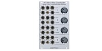
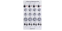
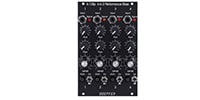
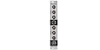
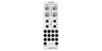
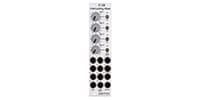
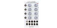
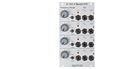
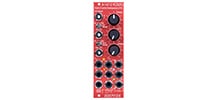
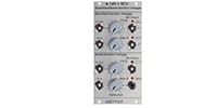
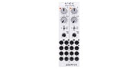
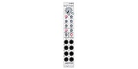
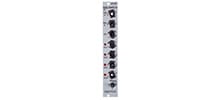
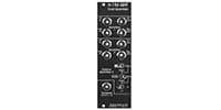
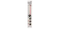
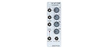
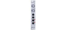
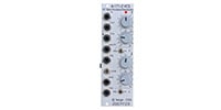
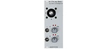
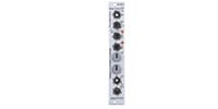
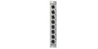
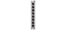
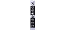
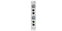
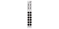
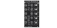
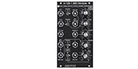
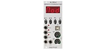
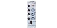
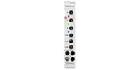
DOEPFER / A-147-4V Dual VC LFO


Variations


Back Order
LFO

Back Order
Morphing Controller
Back Order
ADSR
Back Order
Dual Micro ADSR
Back Order
ADSR
Back Order
VC ADSR / LFO
Back Order
VC ADSR / LFO
Back Order
Quad Poly VCADSR
Back Order
VC Decay / Gate
Back Order
Dual Envelope Controlled VCA
Back Order
Quad Decay
Back Order
Quad AD / LFO
Back Order
Quad ADSR
Back Order
Quad LFO
Back Order
Quad VCLFO / VCO
Back Order
Quadrature LFO
Back Order
LFO 2
Back Order
VCD LFO
Back Order
VCD LFO
Back Order
VCD LFO
Back Order
Dual S&H
Back Order
Dual S&H
Back Order
Quantized/Stored Random
Back Order
Digital Random Voltages

Back Order
Quad LFO
Special Order
Dual Micro ADSR
Special Order
Quad LFO
Special Order
Dual VC LFO
Special Order
Dual VC LFO
Special Order
Quad VC LFO
Special Order
Quad VC LFO
Special Order
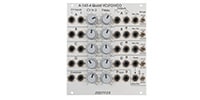
Quad Random Voltages


approx. 0.02 Hz (~ 50 sec) ... 2.5 kHz or approx. 0.0017 Hz (~ 600 sec) ... 220 Hz.
Setting a higher frequency range allows the LFO to be used as a VCO The highest frequency is about 2.5 kHz or about 0.0017 Hz (~600 sec.). The highest frequency is approximately 2.5 kHz.
Each LFO has a reset input for the triangular wave core.
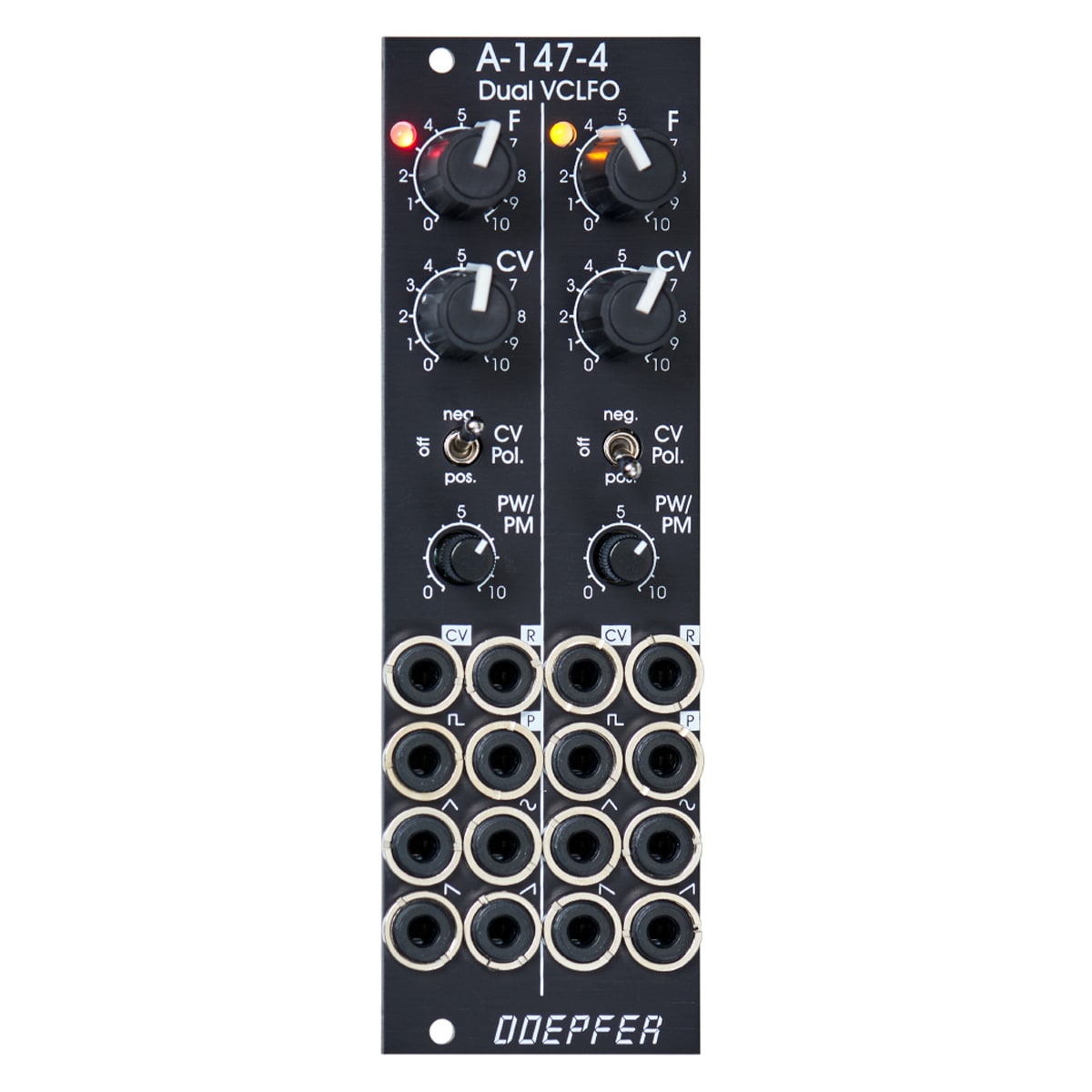
Control
F (FREQUENCY): Manual control of frequency. The frequency range of each LFO can be changed using jumpers.
Frequency range of control F in the high frequency range: approx. 0.075 Hz (~13 sec) ? 1,4kHz
Frequency range of control F in low frequency range: approx. 0.007 Hz (~ 140 sec) ? 125Hz
CV (Control Voltage): Attenuator for the signal input to the CV jack; functions as a frequency fine-tuning knob when no patch cable is connected to the CV jack. This function can be canceled by a jumper.
Switch CV/Pol.: Switches the polarity of the CV input to the CV jack.
PW/PM: Knob for manual and CV control of square wave pulse width.
Acts as a manual pulse width (PW) adjustment when no patch cable is connected to the P jack.
If a patch cable is connected to the P jack, it acts as an attenuator for the incoming CV signal. The pulse width is modulated with 50% as the center (at 0V).
Inputs and Outputs Inputs to the
module are labeled with white letters on a black background. Outputs are labeled with black text.
CV : Voltage input for frequency control.The module is factory adjusted so that the sensitivity of this input is exactly 1V/Oct when the CV control is fully CW.
R : Reset input.Can be edge triggered or level controlled by jumper setting. (See Technical Note for details.) P: Voltage input for pulse width control.
Waveform symbol: Output of the respective waveform (triangular, sine, ascending and descending sawtooth, rectangular) The output voltage range is approximately -5V to +5V (10Vpp), except for the square wave output.
For square wave output only, the amplitude range can be set with a jumper on the rear panel to approximately -5V to +5V or 0 to +10V.
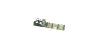
LED : Visual indication of LFO status (lights up based on the triangular wave) Technical note and special features: The fundamental frequency range of each LFO can be selected with a jumper on the rear panel.This setting works to switch between two different capacitor values in the VCO circuit; the ratio of the two frequency ranges is approximately 1 : 11. When the upper range is selected, frequencies from about 0.02 Hz up to 2.5 kHz can be generated. Values in the lower range are from about 0.0017 Hz to 220 Hz. To obtain these full frequency ranges, an external control voltage is required. With frequency control F, you stay within the range of frequencies listed in the control column.
Another option is to reduce the control range of knob F (FREQUENCY) to obtain finer resolution.To do this, the jumper must be removed. The control range F is then reduced to approximately 1:4.5.
With the factory default settings, the starting voltage of the triangular wave output after reset is adjusted to 0V.This means that when the reset signal is input, the triangular wave starts at 0 V and rises.A trimming potentiometer can be used to adjust the starting voltage to another value (e.g., -5V).
Another jumper is used to set the reset operation to edge-triggered or level-controlled. When set to edge-triggered, the rising edge of the reset signal is used for reset (independent of the duration of the "high" state of the reset signal). When set to level control, the voltage level of the triangular wave remains at the starting voltage as long as the reset signal is "high. Only when the reset signal goes "low" does the triangular wave start oscillating.
The following document shows the position and function of the module jumpers and trimming potentiometers: A147_4_trimming_potentiometers_and_jumpers.pdf Please note that failure of adjustment by the customer or failure due to this is not covered under warranty.Please note that failure of adjustment by the customer or malfunction due to such failure is not covered by the warranty.
Width 8HP
Depth 45mm
Current consumption
+12V : 80mA
-12V : 70mA
関連商品
-
¥780(incl. tax)
 In Stock
 -
¥10,800(incl. tax)
In Stock -
¥34,800(incl. tax)
In Stock -
 KORG / SQ-CABLE-6 PATCH CABLE for SQ-1 ミニパッチケーブル
¥1,580(incl. tax)
In Stock -
 MOOG / S.M CABLE 8 6/12/18/24IN Modular patch cable
¥4,950(incl. tax)
 Back Order
 -
 Tiptop Audio / Stackable Cable White 20cm x 5
¥5,698(incl. tax)
Back Order -
 Tiptop Audio / Stackable Cable White 30cm x 5
¥5,698(incl. tax)
 TBA
TBA -
 Tiptop Audio / Stackable Cable White 50cm x 5
¥5,698(incl. tax)
TBA -
 Tiptop Audio / Stackable Cable White 70cm x 5
¥6,050(incl. tax)
Back Order -
 Tiptop Audio / Stackable Cable White 90cm x 5
¥6,050(incl. tax)
Back Order
 KORG / MS-CABLE-YL
 BEHRINGER / EURORACK 104
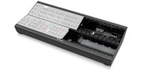 BEHRINGER / EURORACK GO
商品レビューProduct Review


不適切な投稿として報告しますか?
理由
ご協力ありがとうございました
投稿を削除しますか?
投稿されたレビューを削除しました。
DOEPFER
A-147-4V Dual VC LFO
Item ID:369830
36,500 yen(incl. tax)
365Pt(1%)Detail
- 365Pts
通常ポイント
- 365Pts
Total
 Special Order
 - In Stock
- In Stock, can be shipped when order is confirmed.
- Low Stock
- Low Stock, may be sold out soon.
- Scheduled date
- Expected to arrive at Sound House on this date.
- TBA
- Expected date of arrival at Sound House to be determined.
- Back Order
- It needs to be orderd from the manufacturer. Please inquire about the estimated date of arrival.
- Mfr. Delivery
- Must be ordered from manufacturer. Please inquire about the estimated date of arrival.
- Download
- Only the serial number will be sent to your registered email address.
- Special Order
- Made to order item or must be ordered from manufacturer. May take several weeks or months.
- No Longer Available
- Product is no longer available due to having been discoutined or other reasons.
Rating

この商品に関連するセレクションRelated Articles
-
 Discount Sale
-
 Outlet
-
 New Arrivals
-
 Podcast (streaming)
-
 Headphones / Earphones
-
 Microphones
-
 Wireless Equipment
-
 Speakers
-
 Power Amps
-
 Mixers
-
 Processors
-
 Portable PA Systems
-
 Recorders
-
 Karaoke
-
 Guitars
-
 Basses
-
 Ukuleles
-
 Drums & Percussion
-
 Pianos / Synthesizers
-
 Wind Instruments
-
 Stringed Instruments
-
 Japanese Instruments
-
 Harmonicas, Other
-
 Software
-
 DJ & VJ
-
 Stands
-
 Cables & Connectors
-
 Racks & Cases
-
 Lighting
-
 Stage & Truss
-
 Video Equipment
-
 PC PERIPHERALS
-
 Power Supplies
-
 Studio Furniture
-
 Household Items, Other
-
 Alcoholic Beverages
Search by Brand
Brand List


- Sound House
- 〒286-0825 14-3 Shinizumi , Narita City, Chiba
- Monday-Friday 10:00-17:00
- Narita Call Center
- TEL. 0476-89-1111
- FAX. 0476-89-2222
- Tokushima Call Center
- TEL. 0885-38-1111
- FAX. 0885-38-1100
- Showroom Hours
- Monday-Friday 10:00-17:00
closed on Saturdays, Sundays and Holidays
© Sound House

すべてのレビューを見る