


![]()
- Pianos / Synthesizers
- SYNTHESIZER
- Modular synths / sound modules
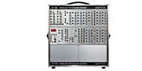
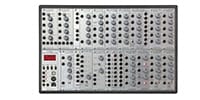
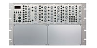
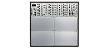
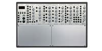
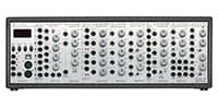
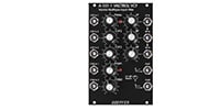
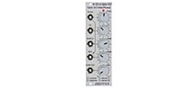
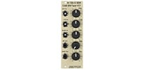
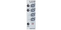
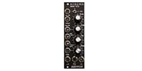
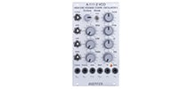
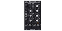
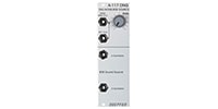
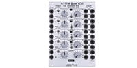
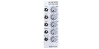
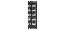
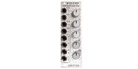
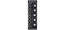
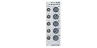
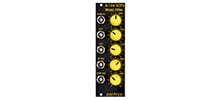
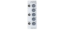
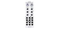
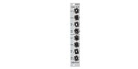
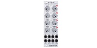
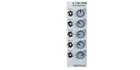
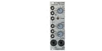
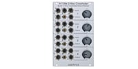
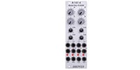
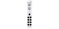
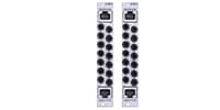
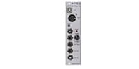
- DOEPFER/A-121s Stereo Multimode VCF
DOEPFER / A-121s Stereo Multimode VCF


Variations


Back Order
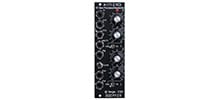
Moog Type VCF / 24dB LPF
Back Order
Moog Type VCF / 24dB LPF
Back Order
12dB Multimode VCF
Back Order
12dB Multimode VCF
Back Order
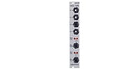
CEM Type VCF 1 / 24dB LPF
Back Order
6/12/18/24dB HPF
Back Order
WASP Type VCF / 12dB
Back Order
WASP Type VCF / 12dB
Back Order
A-125 VC Phase Shifter
Back Order
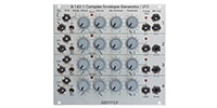
A-127 Triple VCF
BOM Break Out Module
Back Order
Fixed Filter Bank
Back Order
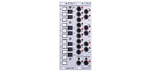
DUAL MULTIMODE FILTER
Back Order
DUAL MULTIMODE FILTER
Back Order
WASP FILTER SLIM LINE
Back Order
WASP FILTER SLIM LINE

Special Order
Mini 12dB Multimode VCF

Special Order
Stereo Multimode VCF

Special Order
Stereo Multimode VCF

Special Order
VC Frequency Shifter 2

Special Order
Frequency Shifter II Expander
-
Special Order
Frequency Shifter II Expander

Special Order
VC Frequency Shifter 2
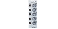
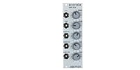
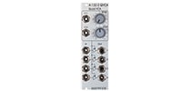
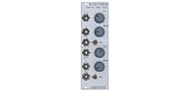
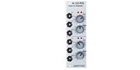


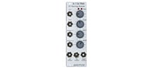
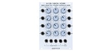
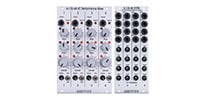
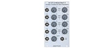
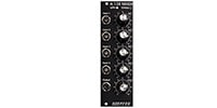
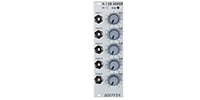
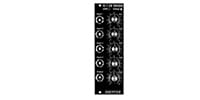
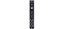
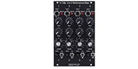
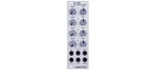
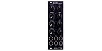
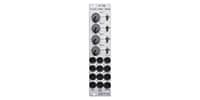
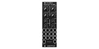
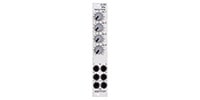

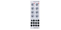
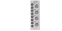
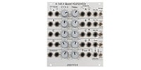
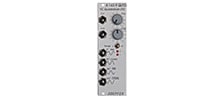
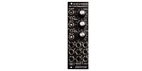
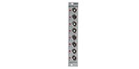

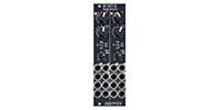
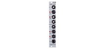
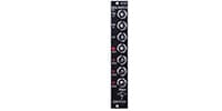
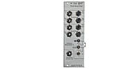
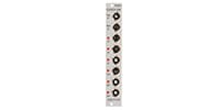
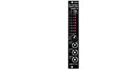
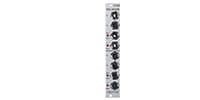

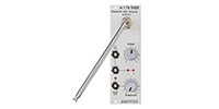
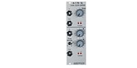
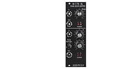
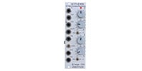
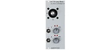
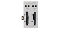
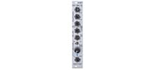
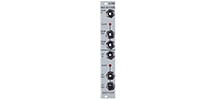
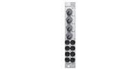


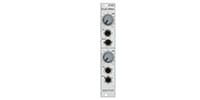
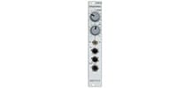
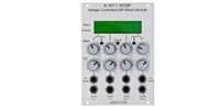
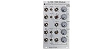
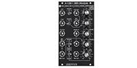
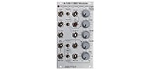
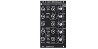
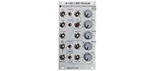
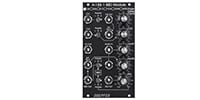
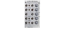
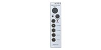
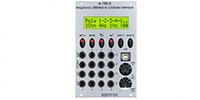

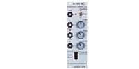
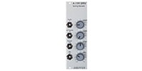
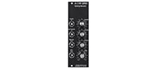
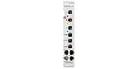
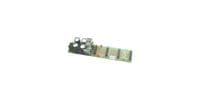
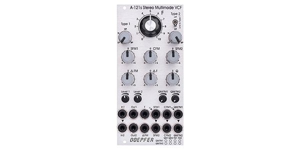
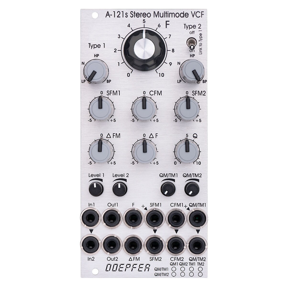
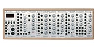
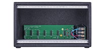
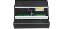
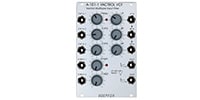
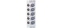
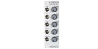
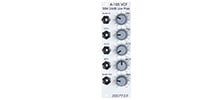
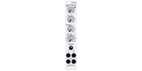
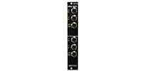
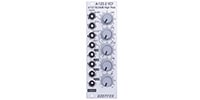
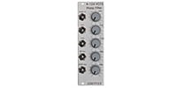
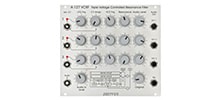
F : Master frequency control for both filters. (Large center knob)
Type 1 / Type 2 : Panning / morphing of filter type. L-N-H-B (Lowpass-Notch-Highpass-Bandpass)
Link to Type 1 : When the switch is set to On, Type 1 also controls Type 2 of Filter 2 (i.e. it controls both filter types simultaneously). (i.e. it controls both filter types at the same time).
SFM1 / SFM2 : Single frequency modulation control (polarizer), connected to corresponding jacks SFM1 / SFM2. (The SFM1 jack is internally connected to a fixed positive voltage, and SFM2 is internally connected to SFM1. Therefore, if no modulation signal is patched to the SFM1 / SFM2 jacks, the SFM1 / SFM2 knob functions as a freqency control for each filter).
CFM : Common Frequency Control, controls two VC polarizers that process the signal connected to the two jacks CFM1 / CFM2. CFM2 is internally connected to CFM1, so the same modulation signal (e.g. envelope generator) The same modulation signal (e.g. envelope generator) can be used for both filters, and the CFM knob controls the levels at the same time.
Delta F: Manually controls the difference in freqency (freqency “spread”) between the two filters. When the knob is set to the center position, the freqency of both will be the same.
Delta FM : Controls the level of the Delta FM signal (jack) and the spread between the frequencies can be controlled by an external control voltage (LFO, ADSR, etc.).
Q : Controls the resonance of both filters simultaneously.
Level 1 / Level 2 : Attenuator for the two audio inputs.
QM/TM1, QM/TM2 : Attenuators for modulation inputs QM/TM1 and QM/TM2.
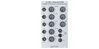
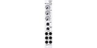
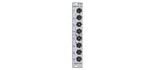
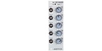
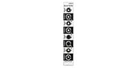
Jacks
In1 / In2 : These are audio inputs. (In2 is internally connected to In1)
Out1 / Out2 : Audio output.
F : Frequency control input for both filters. (~ 1V/oct)
Delta FM : CV signal input to control the freq. spread by the polarizer Delta FM.
SFM1 / SFM2 : Single Frequency Modulation Inputs, CV signals to control polarizers SFM1 and SFM2 SFM1 is connected to a fixed positive voltage and SFM2 is internally connected to SFM1.
CFM1 / CFM2 : Common Frequency Modulation input, CV signal input to control polarizers CFM1 and CFM2. CFM2 is internally connected to CFM1.
QM/TM1, QM/TM2 : The purpose of these jacks/attenuators is set by an internal jumper, where QM stands for Q modulation (QM1=resonance modulation of filter 1, QM2=resonance modulation of filter 2,) and TM for filter type QM/TM1 jack is connected to a fixed positive voltage, and QM/TM2 is connected internally to QM/TM1. The internal jumpers are set as follows when shipped from the factory.
QM/TM1 : QM1, QM2
QM/TM2 : TM1, TM2
* To set the internal jumpers, it is necessary to remove the board on the back of the module. This operation is not covered by warranty. Please contact Fusan Entrepreneurial Support if you wish to change the settings.
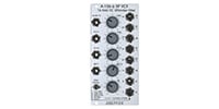
The + sign in the upper left corner of the jack and the 45 degree triangle indicate that the switching contacts of the jack are internally connected to a fixed positive voltage. (SFM1, QM/TM1)
The vertical triangle indicates that the two jacks are internally connected. (In1>In2, SFM1>SFM2, CFM1>CFM2, QM/TM1>QM/TM2)
If the filter is not working as desired, note these module-specific specifications.
SFM1, SFM2, CFM, Delta F, and Delta FM are polarizers, so the center is neutral. If the filter behaves unexpectedly, set these knobs to center.
The SFM1 and SFM2 jacks are also internally connected to a fixed positive voltage when no patch cable is connected. In this case, the SFM1 and SFM2 knobs are centered as neutral and act as additional, individual manual controls for filter 1 and 2 frequencies.
The F, Q, Level 1, Level 2, QM/TM1, and QM/TM2 knobs are neutral in the fully counterclockwise position for standard attenuators. If the filter behaves unexpectedly, QM/TM1 and QM/TM2 should be set fully counterclockwise. The reason for this is that the internal connection between the QM/TM1 and QM/TM2 jacks causes the associated controls to generate CV, which is added to the CV generated by the main controls (Type 1, Type 2, and Q). Which parameters are affected depends on the internal jumper settings. See A121s_trimming_potentiometers_and_jumpers.pdf for more information.
The small circles in the lower right corner of the front panel allow you to mark the function of the QM/TM inputs. As an example, these assignments are available.
QM/TM1 controls QM1, QM/TM2 controls QM2, and filter type is not controlled by external CV.
QM/TM1 controls TM1, QM/TM2 controls TM2, and resonance is not controlled by an external CV.
QM/TM1 controls QM1 and QM2 simultaneously, and QM/TM2 controls TM1 and TM2 simultaneously.
Application
Stereo Filter : Connects two different audio signals to the audio inputs. The output produces a filtered signal. Filtering depends on the position of the knob and the voltage of the applied CV signal.
Serial Mono Filter : Connect a mono signal to audio input 1. Connect a patch cable from audio output 1 to audio input 2. Note that the filter parameters must be set such that the audio signal is output. For example, if low-pass and high-pass are connected in series, the freqency of the low-pass must be higher than that of the high-pass. Otherwise, no audio signal will be output.
Parallel Mono Filter : Connects audio signals to both audio inputs. (Mix audio outputs 1 and 2 using the mixer module (e.g., via internal connection In1>In2).
Width 12HP
Depth 45mm
Current consumption
+12V : 100mA
-12V : 100mA
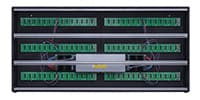
関連商品
-
¥780(incl. tax)
 In Stock
 -
¥10,800(incl. tax)
 TBA
TBA -
¥34,800(incl. tax)
TBA -
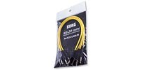
 KORG / SQ-CABLE-6 PATCH CABLE for SQ-1 ミニパッチケーブル
¥1,920(incl. tax)
In Stock -
 MOOG / S.M CABLE 8 6/12/18/24IN Modular patch cable
¥4,950(incl. tax)
 Back Order
 -
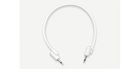
 Tiptop Audio / Stackable Cable White 20cm x 5
¥5,698(incl. tax)
Back Order -
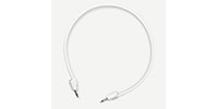
 Tiptop Audio / Stackable Cable White 30cm x 5
¥5,698(incl. tax)
Back Order -
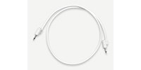
 Tiptop Audio / Stackable Cable White 50cm x 5
¥5,698(incl. tax)
Back Order -
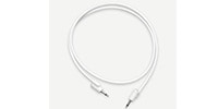
 Tiptop Audio / Stackable Cable White 70cm x 5
¥6,050(incl. tax)
Back Order -
 Tiptop Audio / Stackable Cable White 90cm x 5
¥6,050(incl. tax)
Back Order
 KORG / MS-CABLE-YL
 BEHRINGER / EURORACK 104
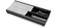 BEHRINGER / EURORACK GO
商品レビューProduct Review


不適切な投稿として報告しますか?
理由
ご協力ありがとうございました
投稿を削除しますか?
投稿されたレビューを削除しました。
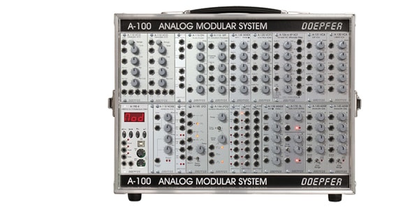
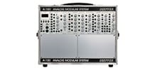
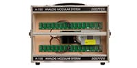
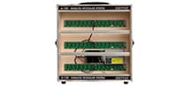
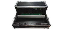
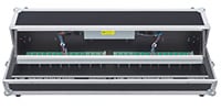
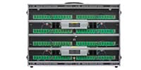
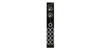
DOEPFER
A-121s Stereo Multimode VCF
Item ID:369810
48,950 yen(incl. tax)
489Pt(1%)Detail
- 489Pts
通常ポイント
- 489Pts
Total
 Special Order
 - In Stock
- In Stock, can be shipped when order is confirmed.
- Low Stock
- Low Stock, may be sold out soon.
- Scheduled date
- Expected to arrive at Sound House on this date.
- TBA
- Expected date of arrival at Sound House to be determined.
- Back Order
- It needs to be orderd from the manufacturer. Please inquire about the estimated date of arrival.
- Mfr. Delivery
- Must be ordered from manufacturer. Please inquire about the estimated date of arrival.
- Download
- Only the serial number will be sent to your registered email address.
- Special Order
- Made to order item or must be ordered from manufacturer. May take several weeks or months.
- No Longer Available
- Product is no longer available due to having been discoutined or other reasons.
Rating
この商品に関連するセレクションRelated Articles

-
 Discount Sale
-
 Outlet
-
 New Arrivals
-
 Podcast (streaming)
-
 Headphones / Earphones
-
 Microphones
-
 Wireless Equipment
-
 Speakers
-
 Power Amps
-
 Mixers
-
 Processors
-
 Portable PA Systems
-
 Recorders
-
 Karaoke
-
 Guitars
-
 Basses
-
 Ukuleles
-
 Drums & Percussion
-
 Pianos / Synthesizers
-
 Wind Instruments
-
 Stringed Instruments
-
 Japanese Instruments
-
 Harmonicas, Other
-
 Software
-
 DJ & VJ
-
 Stands
-
 Cables & Connectors
-
 Racks & Cases
-
 Lighting
-
 Stage & Truss
-
 Video Equipment
-
 Computer Accessories
-
 Power Supplies
-
 Studio Furniture
-
 Household Items, Other
-
 Alcoholic Beverages
Search by Brand
Brand List


- Sound House
- 〒286-0825 14-3 Shinizumi , Narita City, Chiba
- Monday-Friday 10:00-17:00
- Narita Call Center
- TEL. 0476-89-1111
- FAX. 0476-89-2222
- Tokushima Call Center
- TEL. 0885-38-1111
- FAX. 0885-38-1100
- Showroom Hours
- Monday-Friday 10:00-17:00
closed on Saturdays, Sundays and Holidays
© Sound House

すべてのレビューを見る