Hello! Recently I’ve been sitting on the sofa after dinner, only to fall asleep without realizing it. Then when I wake up, it’s already past 4 a.m.
There’s something oddly relaxing about that time after dinner, so it happens every once in a while.
I know that after finishing my meal and cleaning up, I should either do something else or just take a bath right away.
But for some reason, I always end up sitting on the sofa and just melting into it.
And doing that during the change of seasons is actually pretty dangerous.
When it starts to feel a bit chilly and I start to wonder, “Should I turn on the heater yet? Maybe not?”—that early morning cold is really hard on the body.
Seriously, it can mess up your health.
And, actually… I turned on the heater twice just in October alone. Even though I know it’s bad for you… sigh, I’m hopelessly foolish sometimes.
Fortunately, I haven’t gotten sick yet, but if I let my guard down, I could really harm my body—so everyone, please be careful too!
Since I’ve been working on building the VOODOO-1 since last month’s blog, this time I’ll be continuing from there.
This session covers attaching the components to the circuit board and drilling holes in the case, so I’d be happy if you read through to the end.
First, I start attaching the components to the circuit board. Basically, it’s easier to begin with the shorter ones.
So, I start by attaching the resistors and diodes.
I think everyone has their own preferred method, but here’s how I do it.
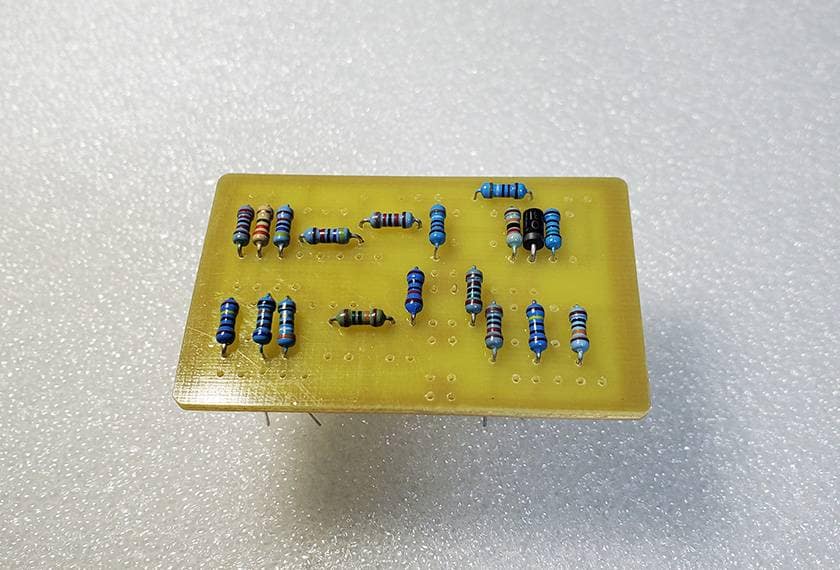
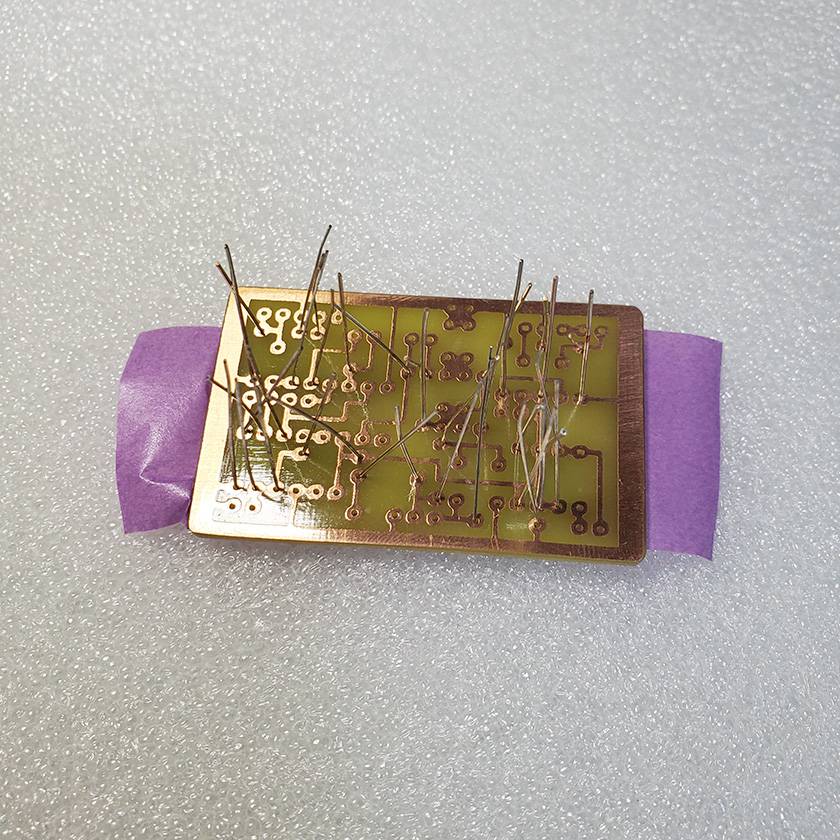
I insert all the resistors and diodes into their holes.
Then, I place masking tape over them from above to hold them in place.
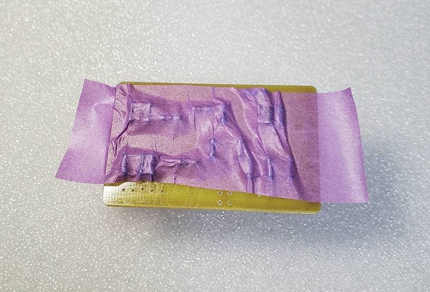
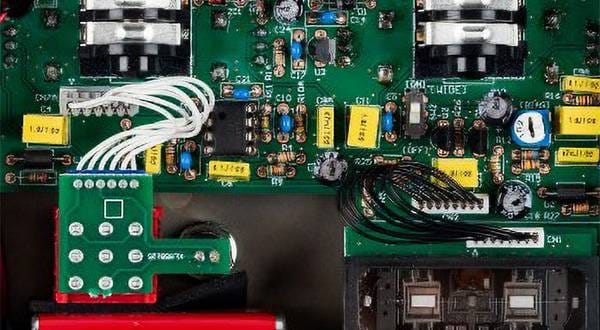
After that, I flip the board over, snip off the excess leads with a quick snap, and solder them. It ended up looking like the next photo.
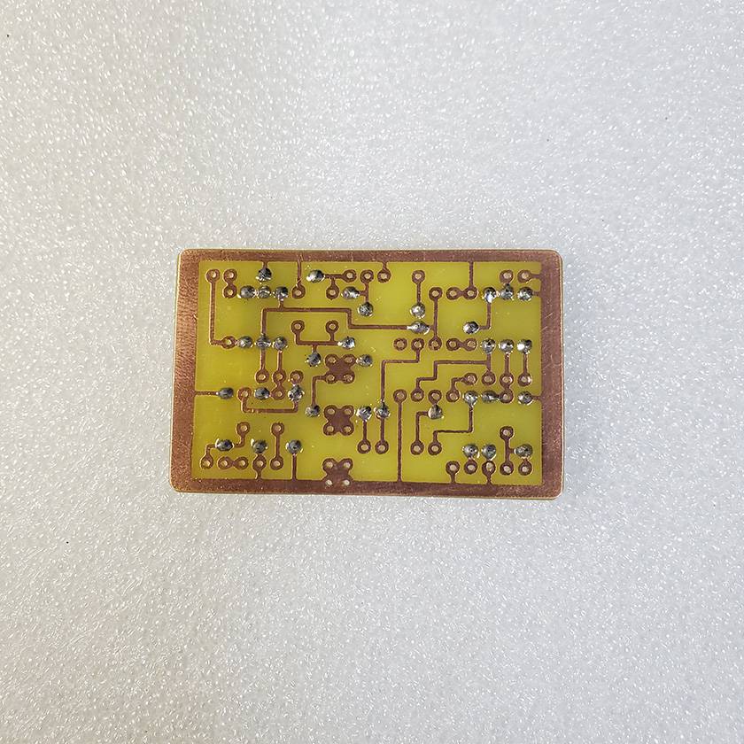
I have to admit, it’s kind of a power move—but since I believe that the foundation to making things is to first make sure they are secure. I think it actually makes a lot of sense.
After trying various methods, so far this one feels the easiest for me.
Then, I continued with the sockets → film capacitors → electrolytic capacitors in the same way, and that completes the circuit board.
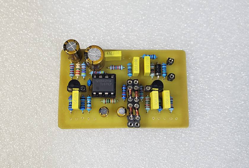
This time, I made the clipping diodes socketed so that I can swap them out later.
In the DIY effects pedal community, opinions on this tend to be divided, but personally, I think if the builder is happy with it, that’s what matters. So, I often use this method for the clipping section.
Next up is the operational amplifier.
The original uses an LM308, but that op-amp has become pretty rare these days, and I don’t have any in my possession. So, my attitude was basically, “Well, I’ll just throw in a TL071 for now.”
In the DIY RAT pedal scene, which uses the same kind of op-amp, it seems common to use the OP07, the one used in current production models, but I didn’t have any of those either.
Honestly, I hardly ever use single op-amps, so I don’t keep many around.
They’re also a bit pricey.
Since I’m using a different op-amp from the original, I’m sure people who know the details will have various thoughts on this—like the difference in slew rate and so on—but please overlook that for now.
If I can get my hands on one later, I plan to replace it.
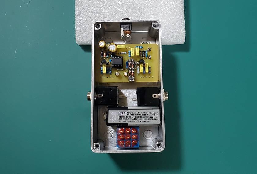
And with that, the circuit board is done.
Next, I’ll move on to working on the case.
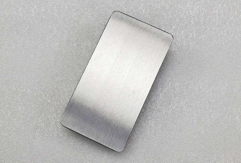
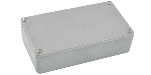
Technically, when talking about aluminum housings, it’s probably more accurate to call them enclosures, but I think “case” is easier for readers to understand—so in this blog, I’ll stick with “case”.
Now, I would like to say that I’m using a TAKACHI/TD6-11-3N, but unfortunately, I’ll actually be using some random case I had lying around at home. I don’t even know what brand it is—or if it even has a brand name, honestly.
By the way, the TAKACHI/TD6-11-3N is an excellent product with outstanding durability, and our company carries it, so I’ll include the link here:
When you build your own projects, please consider purchasing from us!!!!!
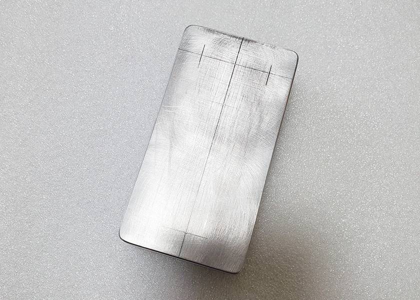
Since I’ll be painting it this time, I will start by smoothing out the surface of the case with sandpaper, both to level it and to help the paint adhere better.
After that, I mark the drilling measurements according to my preferences, and it looks something like this.
Next, I will mark the drilling points with a center punch and then go scrreeeech with the drill to make the holes.
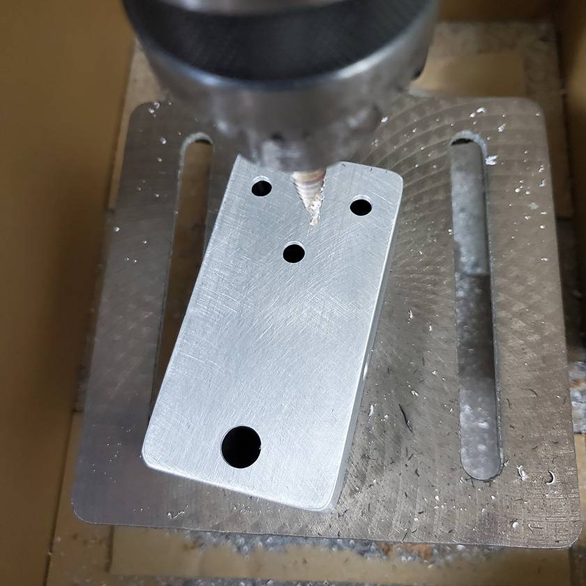
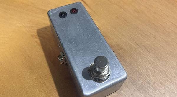
It’s starting to look like something familiar now.
You might notice that the hole for the footswitch is placed quite low, so it may look a bit odd—but personally, I find it easier to step on that way, and I prefer it.
I think this is actually a pretty common “DIY effects pedal” kind of thing.
Finally, before painting, I seal up the holes with masking tape, and that wraps up today’s work.
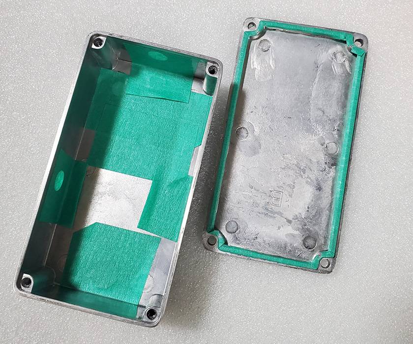
There seem to be two schools of thought here—the “seal the holes” camp and the “don’t seal” camp—but I usually seal them for no particular reason.
Ah—but now that I’m writing this blog, thinking about it… does it really make much difference in the process either way? Or, maybe not masking the holes is actually easier?
Well, the amount of paint that gets inside the case would change, but it doesn’t really seem to cause much trouble either way…
Next time I build one, I might try doing it without sealing the holes.
And with that, today’s work is done—for now.
Oh, and before putting on the masking tape, I did a quick test assembly just to check how it all fits together.
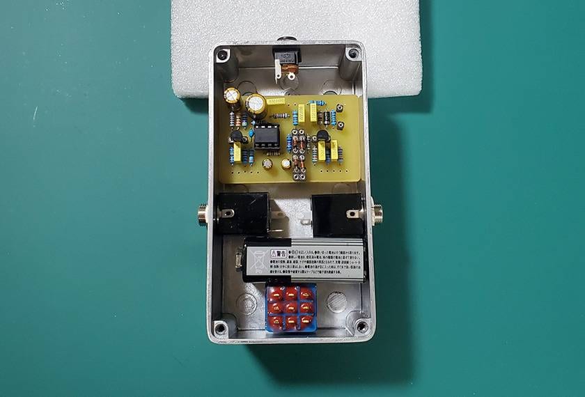
Whenever I do a trial assembly, I can imagine the completed form, it really lifts my spirits up.
How was it?
This time I was able to gradually see the overall form of the effects pedal, from attaching components to the circuit board to working on the case, so I really enjoyed the process.
In the next blog post, I plan to move forward with painting the case.
Since I’m making it myself, it’s only natural that I want to customize it to my own liking!!
I’ll keep working hard, so please look forward to the next update as well.
Thank you very much for reading the blog all the way to the end.
I’ll see you again on the Sound House Staff Blog. Sayonara.


![[Part 1] A High School Guitarist Wants to Build a Pedal - Circuit Board](/contents/uploads/thumbs/5/2024/2/20240228_5_25785_1.jpg)
 ギターパーツの沼
 DIY ギターメンテナンス
 ベース用エフェクターの種類
 お手入れに必要な道具
 エフェクターのつなぎ方
 エフェクターの種類