In this blog post, I’ll be teaching you how to make effective use of compact effects pedals that everyone probably has at least one of but no longer uses.
The reasons you stopped using them are likely varied: they don’t match the genre you play, you found something you like better, or you simply got bored of them.
However, letting them just sit unused is such a waste.
Let’s take another look and give them some radical modifications so they can produce a sound that suits your personal taste.
I’ll be posting updates whenever the mood strikes, but for now, the first sacrifice will be an overdrive pedal.
I’ll explain in detail what happens when you tweak which parts and how the sound changes.
In terms of content, this is archive-worthy material.
First, I want you to learn the basics of distortion circuits.
This is a circuit diagram using an OP-AMP (operational amplifier), which is the most basic of the fundamentals.
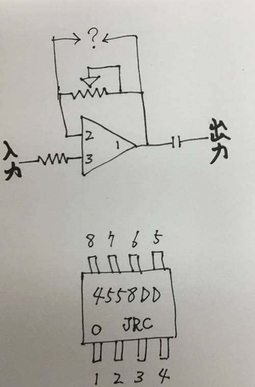
Except in special cases, a dual op-amp—containing two circuits within a single package—is typically used.
In the diagram, the part labeled 4558DD represents the OP-AMP package, with numbers shown for each pin. Pins 1–3 form one circuit, while pins 5–7 form the other circuit.
Pin 4 is ground, where the power supply negative and signal negative are connected, and pin 8 is where the power supply positive is connected.
Now, I’ve talked about OP-AMPs before, but with dual OP-AMPs, almost any of them will produce sound.
However, surprisingly little information exists that clearly verifies the differences in sound. This is just my personal opinion, but I’d like to share what I found from trying several of them.
- JRC-4558D (Japan Radio Company): Quite standard for effects pedals; not Hi-Fi.
I’m showing this as a reference so all of you can get an idea of what other OP-AMPs are like. - JRC-4559D (Japan Radio Company): A model with improved high-frequency characteristics compared to the JRC-4558D. Characterized by good clarity and a noisy nature.
- JRC-4580D (Japan Radio Company): Flat output from low to high frequencies with no strong coloration. Probably the most Hi-Fi among the 4558 family.
- BA-4558 (ROHM): Very thick sound with muffled highs. Poor clarity, but low perceived noise.
- CXA-4558 (Sony): I felt like I’d heard this sound somewhere before—it’s the same sound as the glossy JRC-4558D from the 1970s. Strong lows and highs, with an overall bright character.
Although labeled as a Sony, the glossy surface suggests it is likely a JRC OEM product.
Simply put, the nuance of the distortion changes depending on what you connect to the question mark in the circuit diagram.
Normally, alternating diodes are connected there, but the circuit will distort even without these diodes, and it will also distort if you add many of them.
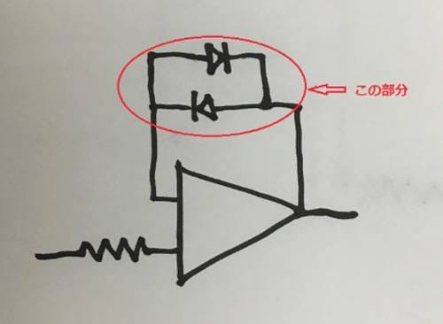
The orthodox wiring methods are as follows.
■ Pattern 1
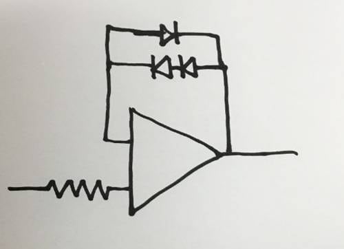
■ Pattern 2
■ Pattern 3
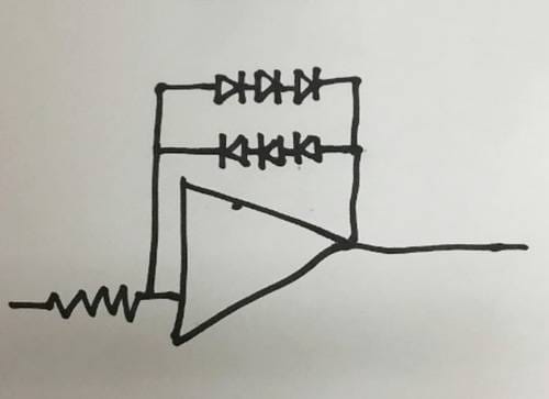
The nuance changes infinitely depending on the diode model, the number of diodes used, and how they are connected.
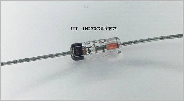
The diodes used are germanium diodes and switching diodes.
Next, in the section where those diodes are connected, there is often a variable resistor (gain or volume) connected at the same time.
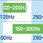
By changing the resistance value, you can increase the amount of distortion (for example, changing a 100 kΩ pot to 250 kΩ increases the distortion by 2.5 times, and a 500 kΩ pot increases it by 5 times).
However, increasing the amount of distortion also increases noise, makes the OP-AMP more prone to oscillation, and can result in a heavily compressed, dirty sound, so caution is required.
Next, at the connection points of that pot, there is usually a capacitor connected in parallel.
This is used to remove unnecessary noise and suppress OP-AMP oscillation.
Numerically, the value is not very large (for reference, the ever-popular TS9 uses 51 pF, and the OD-1 has 18,000 pF on the second stage of the OP-AMP), but this component contributes to how muffled or smooth the sound becomes.
Since an example has come up, let’s continue the explanation using the TS-9.
The first component the input signal passes through is not an OP-AMP, but a transistor.
Here, a very common transistor called the 2SC1815 is used.
The role of this transistor is to lower the input signal’s impedance, so even if you replace it with a different transistor (in fact, almost anything), the sound will hardly change.
However, the transistor in the later stage is a slightly different story.
This section, which finalizes the distortion character and high-frequency response and adjusts the output level, shows noticeable differences depending on the part number used.
A standard NPN transistor with a power supply voltage rating of 12 V or higher is sufficient.
Personally, I like to use something like the 2SC2240.
This time, I introduced four points: the OP-AMP, diodes, transistors, and capacitors.
There are many other points that can be modified, but for now, start with these four.
By replacing any one of them (or all of them), you should be able to clearly hear the changes.
Modifying things is up to the individual, but everything should be done at your own risk.
It’s best to decide on the sound through a cut-and-try approach with each component.
Until next time.

![[Part 0] A High School Guitarist Wants to Build a Pedal - Tools and Preparations](/contents/uploads/thumbs/5/2024/1/20240122_5_25301_1.jpg)

 【初心者向け】エフェクター講座
 あなたのエフェクターボード見せてください
 ベース用エフェクターの種類
 配線カスタマイズ 第1回
 パーツの配線を知ろう
 エフェクターの種類