First, an Apology and a Correction.
There was an error in the circuit diagram posted in the previous blog, and we are re-uploading the corrected version. The wiring of the DI I personally created was not incorrect; it seems I simply made a mistake when drawing out the diagram for the blog. I sincerely apologize for this.
I also received several emails from dedicated readers pointing out the mistake.
While I deeply regret the error, I was also pleased to see how thoroughly people are engaging with the content.
Please don’t hesitate to point out any future mistakes.
Here is the correct circuit diagram.

The input section connected to transistor Q1 was mistakenly crossed, but the part where the 470K resistors are connected should not go directly into Q1. Only the section where the 0.1uF capacitor and 1MΩ resistor are combined should be input to Q1.
Additionally, some readers pointed out that it was unclear which transistor, Q1 or Q2, is NPN or PNP. To clarify, I’ve added an example using BC550 and BC560 transistors: Q1 is NPN, and Q2 is PNP.
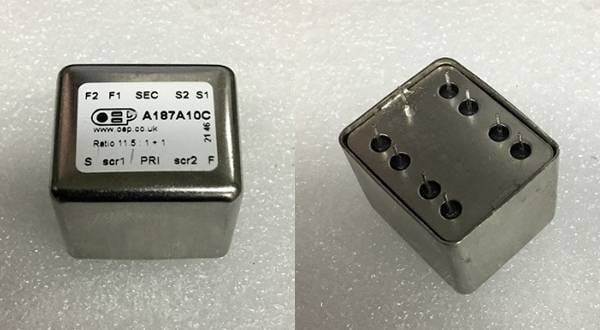
There were also questions about which pins on the transformer correspond to which connections. Please refer to the datasheet of the transformer used in this project for details.
In the previous blog, I assumed that the basic DI circuit was understood, so I’d like to go a step further and modify (or improve?) it to make it even more powerful. While it’s perfectly fine to build the basic DI circuit as is and stop there, I want to note that the modifications in this post are specifically tailored for use with a bass guitar.
In live house settings, the DI signal is connected directly to the PA mixer, so the sound from the bass amp on stage doesn’t reach the PA mixer at all. Unless the sound is being picked up from the bass amp's speaker using a microphone, the sound coming from the DI is not much different from connecting the bass directly to the mixer with a low-impedance signal. No matter how great the amp sounds on stage, the sound that reaches the mixer is the raw tone coming directly from the bass itself.
With that in mind, I figured the best approach would be to make the sound sent to the mixer as impressive as possible. This circuit was designed with that straightforward idea, and I determined the component values through numerous trials, repeatedly connecting a bass and fine-tuning the circuit.
Of course, if you’re not satisfied with the results, feel free to adjust the values yourself or even choose not to use the filter. That's why I've included a switch to toggle between the normal signal and the filtered one.
The circuit is a basic notch filter, with the frequency and amount of cut tailored to specific needs.
The components used in this circuit are as follows:
- 1/4W Metal Film Resistors: 18KΩ × 2 and 10KΩ × 1
- Film Capacitors: 0.01uF × 3
- ON-ON 6P Toggle Switch: × 1
For my build, I used DALE RN-60 resistors and Siemens plastic-molded multilayer film capacitors.
Here is the filter circuit diagram.

Apologies for the rough hand-drawn diagram. The output level slightly decreases when passing through the filter, but this can be easily compensated by increasing the input gain on the mixer. In fact, this should allow you to enjoy a rich, punchy, and satisfying bass sound.
You can choose between a 10KΩ or 12KΩ resistor. The 10KΩ option is tailored for a "zunbin" sound, ideal for bass slapping, while the 12KΩ option retains a bit more midrange, resulting in a slightly more balanced tone.
This filter circuit should be inserted at the red circled section in the diagram.
Even if you accidentally swap the IN and OUT connections, it won’t cause any issues. However, to toggle the filter on and off, connect it to an ON-ON 3P toggle switch. This allows you to easily switch the filter in and out of the circuit as needed.

Since the signal impedance is already reduced, you don't need to worry much about signal loss from the switch. However, if you use a cheap switch, you might experience noise when toggling or issues like unstable volume due to poor internal contact. Therefore, I recommend using a high-quality switch.
I personally used a silver contact switch from ALCO. I remember finding them at a parts shop in Akihabara years ago for just 50 yen each, and I had to resist the urge to freak out with excitement as I bought all of them.

With that, the DI circuit and construction process are complete.
I encourage you to personalize the case with lettering or stickers—whatever design you like—to make it your own. I guarantee the sound quality will be so impressive that you'll forget about the costs incurred up to this point.
As long as you don’t damage the transformer, I recommend experimenting by swapping out parts multiple times. Since the circuit is simple, rebuilding or modifying it shouldn't be too difficult, and I hope you’ll have fun thoroughly using and enjoying your creation.
I've received enthusiastic support emails regarding this DIY blog, and I sincerely thank you for them. Your encouragement means a lot to me.
For the next installment of the "Shocking DIY Series," I plan to cover the definitive power supply! Stay tuned.


![[Guitarist’s Perspective] Equipment that is Thought to Improve Sound Just by Passing it Through Part 1 - Direct Boxes](/contents/uploads/thumbs/2/2023/2/20230202_2_21077_1.jpg)

![[PA] First direct box DI](/contents/uploads/thumbs/5/2020/11/20201125_5_11656_1.jpg)
![[2023] Hot Selling DI Boxes!](/contents/uploads/thumbs/2/2019/12/20191220_2_8749_1.jpg)

 第2弾 あなたのエフェクターボード見せてください
 【初心者向け】エフェクター講座
 あなたのエフェクターボード見せてください
 ベース用エフェクターの種類
 エフェクターのつなぎ方
 エフェクターの種類