Finally, the circuit explanation and construction steps are here.
I was astonished when testing the sound quality on the prototype. Although it lacks any special features due to the use of an ancient circuit design, it fulfills the basic functions of a direct box. The reason for my astonishment lies in its sound quality.
I conducted a comparison with a standard DI, and this new DI stands out with its remarkable clarity in each note and its impressive depth from the low to mid frequencies, especially when playing bass. The sound is so exceptional that I could play for hours.
Recent standard DIs have a clean but hollow and light sound. While some might describe it as "clean," it lacks depth and richness. In contrast, this DI delivers an especially dense sound with well-separated low frequencies. Even when producing clean tones, it retains a rich, lingering quality. Despite having no harsh frequencies, it still manages to capture subtle nuances with excellent balance.
When using a DI with an acoustic guitar, it often emphasizes the string noise, resulting in a jarring and unpleasant sound. However, this DI excels in output balance, accurately reproducing even the subtle nuances of your touch.
To further improve the design, I started by creating a basic version and then added a notch filter, along with a switch to enhance the bass sound, making it even thicker (and the result is an amazing sound).
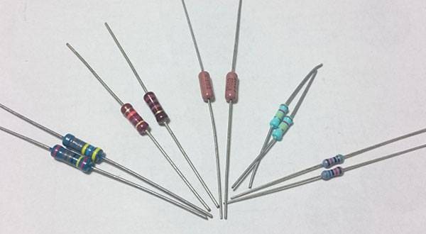
As I mentioned in the previous section about components, the discrete circuit has a minimal number of parts, so the sound quality changes drastically depending on the components used (in this case, the sound quality is particularly influenced by the transistors).
Now, here’s the complete circuit diagram.

Circuit diagram updated.
Apologies for the handwritten version, but as long as it's readable, that's what matters! So please bear with me.
This is the basic version for now.
I've also made modifications to incorporate a filter into this basic circuit, but I’d like you to first understand and build this version.
As you can see from the circuit diagram, the power is supplied via phantom power from a mixer or similar device. Unlike recent DIs that have built-in gain for line input connection, this DI sends a balanced signal to the mic input, which necessitates the use of phantom power.
Naturally, the quality of the mic preamp connected after this DI will also play a crucial role, so I recommend avoiding the use of a cheap mixer for this setup.
This simple DI box features one instrument input, one parallel output (to connect to an amp), and one balanced output (XLR) for connection to a mixer. Additionally, it includes a ground lift switch (used to eliminate noise caused by ground loops) and a powerful notch filter switch (I'll cover this circuit later).
For the enclosure, I'm using a TAKACHI (Japanese-made) case, model number HEN110412S.
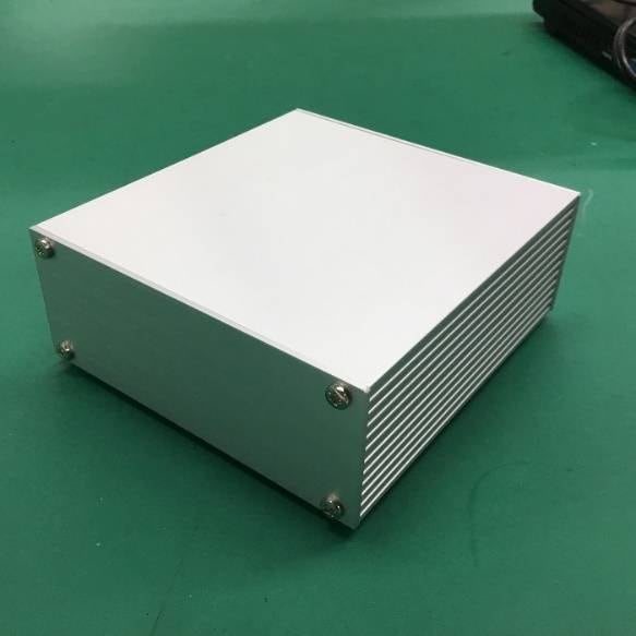
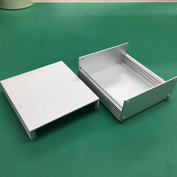
The case is quite stylish, featuring heat dissipation fins on both sides. Since it's made entirely of aluminum, you can also expect excellent shielding. Another advantage is its simplicity—only four screws need to be removed for disassembly or internal inspection.
Now, here's the drilling guide for the front and rear panels.
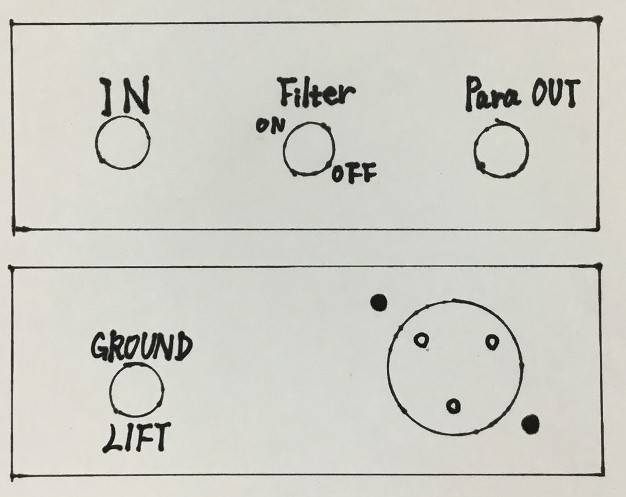
The diagram may look a bit uneven due to my unfamiliarity with drawing shapes, so please bear with me.
For the top panel, the three holes include two 10mm diameter holes on either end, with a 6mm hole in the center. On the bottom panel, the small hole on the left is 6mm in diameter, the large hole is 18mm, and there are two 3mm holes positioned diagonally above and below the large hole.
Since the aluminum sheet is easy to bend, don’t force the work; instead, take your time and proceed patiently.
That’s all for now.
In the next session, I'll explain the superb notch filter circuit and how to incorporate it to make this DI truly unbeatable.
Stay tuned!


![[PA] First direct box DI](/contents/uploads/thumbs/5/2020/11/20201125_5_11656_1.jpg)
![[2023] Hot Selling DI Boxes!](/contents/uploads/thumbs/2/2019/12/20191220_2_8749_1.jpg)
 ポータブルPAシステム特集
 CLASSIC PRO 簡易PAシステム特集
 簡易PAシステム タイプ別おすすめランキング
 Mackie PAスピーカー比較表
 簡易PAセットとは
 PAシステム講座