The Role of the Buffer
When the signal from an electric guitar travels through an effects board and reaches the amplifier, surprisingly many changes to the sound quality occur. Particularly when using multiple effects or long cables, issues like high-frequency loss and muddiness can arise. To solve these problems, a buffer is used. At first glance, a buffer may seem like an effect that doesn't change anything, but in reality, it plays a crucial role in transmitting the guitar's sound as it is. So, what kind of effects does a buffer have in practice? I measured the frequency characteristics of the guitar's signal path to find out.
Two Methods for Measuring Frequency Characteristics
When examining the frequency characteristics of a given signal path, there are broadly two ways to measure it. The first method involves inputting white noise and performing a Fourier transform on the output. The second method involves inputting a sine wave while changing its frequency and observing the output amplitude at each frequency. Each of these methods has its own advantages and disadvantages.
White Noise Method
White noise contains all frequency components uniformly, so by inputting white noise and performing a Fourier transform on the resulting signal, the system's frequency characteristics can be obtained. The advantage of this method is that the amount of work required is minimal, and in theory, all the necessary data can be gathered with just one measurement. However, the downside is that the equipment used for measurement needs to have high performance. Firstly, the signal source that generates the white noise must be able to produce uniform white noise across the desired frequency range. Additionally, since white noise is a random signal, its frequency characteristics over short time intervals will not be uniform. Therefore, the measuring equipment used to analyze the output must be capable of storing waveforms for a sufficiently long period of time. Another disadvantage is that due to the Fourier transform, it can be difficult to correctly analyze the results without a certain level of knowledge in signal processing.
- Good points
- Less measuring effort
- Bad Points
- Measuring equipment specifications required are more stringent
- Basic knowledge of signal processing is necessary
Frequency Sweep Method
The method of sweeping the frequency of a sine wave while checking the amplitude of the output has the opposite merits and demerits compared to the white noise method. For the signal source, it only needs to be able to produce a basic sine wave, and for the measurement equipment that collects the output data, it is sufficient to acquire data for a few cycles to obtain highly accurate amplitude data. When analyzing the results, as long as division can be performed, the amplitude ratio of the input and output sine waves can be easily calculated. The downside is the effort and time required for measurement. The process of changing the frequency of the input signal and checking the amplitude of the output signal must be repeated for each frequency point for which data is needed, and if you want to collect finer data, the amount of work increases proportionally.
- Merits
- The theory is simple
- Can be performed with inexpensive measurement equipment
- Demerits
- The amount of work is enormous
I had a measurement device that could generate noise, but when checking the spectrum, it was not ideal white noise. Therefore, in this article, measurements will be carried out using the frequency sweep method.
Measurement Preparation
Measurement Equipment
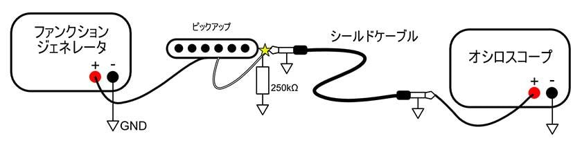
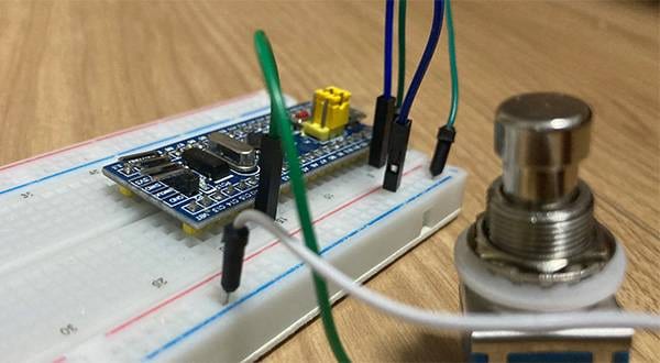
The connection diagram for measuring the frequency characteristics of shielded cables is as follows.
Measurement System
The function generator is a measuring instrument capable of generating sine waves, square waves, and various other signals with arbitrary frequencies and amplitudes. At Sound House, the NTS-2, which integrates with an oscilloscope and other equipment, is available for sale.
Since it's referred to as "a must-have for any studio", many of you might already own it. In this article, I will use the Hantek HDG3022B model. The output impedance is 50Ω, but the DC resistance of the pickup is 4.6kΩ, so the error is negligible. The pickup used is the rear pickup of a Bacchus BST-1M guitar. I had kept the original pickup that was removed when I swapped it out for a single-sized humbucker, so I decided to use it this time. The 250kΩ resistor between the pickup output and ground serves as a substitute for the volume pot. I didn't have any parts available to replace the tone pot, so I omitted that for this test. Since the pickup was originally the rear pickup, in a way, it can be said that I'm recreating the original state. I didn't have a 250kΩ resistor at hand, so I combined three resistors to make 250kΩ (the actual measurement is 254kΩ).
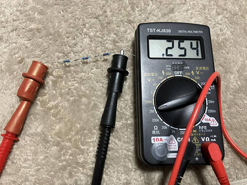
250kΩ resistor
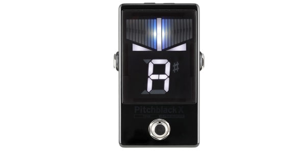
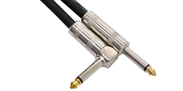
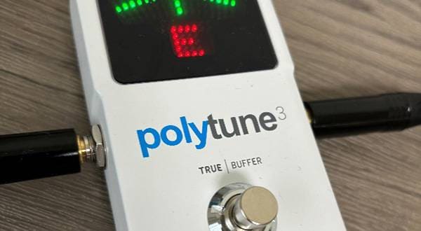
Since I don't have a standalone buffer, I will use the one built into Korg's pedal tuner, the Pitchblack X. The effect of having or not having the buffer will be compared by inserting with or without the Pitchblack X at the star-marked point in the measurement system. For the shielded cable, I will use the CLASSIC PRO GIC030R.
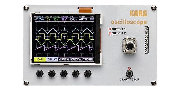
An oscilloscope is a measuring instrument that can measure the time waveform of electrical signals. As mentioned above, Sound House offers the NTS-2 product. In this article, I will use the Rigol DS1104Z Plus. The input impedance of typical guitar amplifiers is said to be around 1MΩ, and since the input impedance of the DS1104Z Plus is also 1MΩ, it can serve as a substitute for the amplifier's input impedance.
Measurement Parameters
The audible frequency range for humans is 20Hz to 20kHz, and in this article, I will make 201 measurements evenly distributed on a logarithmic scale within this frequency range. "Evenly distributed on a logarithmic scale" means that the ratio between adjacent frequencies is constant. Specifically, the frequencies to be measured are 20.00Hz, 20.70Hz, 21.43Hz, ..., 19.32kHz, and 20.00kHz. The amplitude of the sine wave generated by the function generator will be set to 1V.
Measurement Results
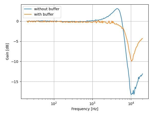
The data obtained from the measurements are displayed in a graph. The horizontal axis represents the frequency on a logarithmic scale, while the vertical axis represents the gain, calculated from the input-output voltage ratio and converted to dB.
When comparing the case with a buffer (orange) and the case without a buffer (blue), it is clear that the frequency response fluctuations are generally smaller with the buffer. The flatter the overall shape of the graph, the more it indicates that the original signal is transmitted to the output without being processed. This confirms that inserting a buffer effectively suppresses the characteristic changes of the signal.
Upon closer observation, the graph without the buffer (blue) shows a peak in gain near 5kHz. This peak is caused by resonance due to the coil of the pickup and the stray capacitance of the shielded cable. By inserting the buffer, this resonance is prevented, and the gain spike at 5kHz is suppressed.
Additionally, in the case without the buffer, a sharp decline in gain is observed in the high-frequency range. This is also due to the interaction between the pickup coil and the stray capacitance of the shielded cable, but the introduction of the buffer significantly alleviates this effect.
Regardless of the presence of the buffer, both graphs show a point of minimum gain around 10kHz, where the gain decreases. Some may wonder whether the sound should be transmitted as is when using a buffer, but this decrease in gain is due to the inherent characteristics of the pickup and cannot be canceled by the buffer. In fact, by using the buffer to eliminate the influence of the shielded cable, the pure frequency characteristics of the pickup are revealed.
In closing
Finally, the buffer plays an important role in the transmission of guitar sound. As the measurement results clearly show, the presence or absence of a buffer greatly affects the interaction between the pickup and the shielded cable, resulting in noticeable differences in frequency characteristics. For guitarists, a buffer is an essential tool to preserve the instrument's original tone. Especially when using long cables or connecting multiple effects, understanding and utilizing the effect of a buffer will help achieve more of that ideal guitar sound.
The “sound & person” column is made up of contributions from you.
For details about contributing, click here.


![[2025 Edition] 5 Recommended Pedals from TC Electronic!](/contents/uploads/thumbs/2/2023/8/20230821_2_23669_1.jpg)
 CLASSIC PRO
 【初心者向け】エフェクター講座
 あなたのエフェクターボード見せてください
 ベース用エフェクターの種類
 エフェクターのつなぎ方
 エフェクターの種類