Another apology.
In the previous post, I mentioned that the second part would be about the power supply, but due to various issues, it is not yet ready for release.
Therefore, we have urgently replaced it with an extended buffer edition.
I apologize to the readers who were looking forward to it.
How was the first part, "The DI Edition," which was highly popular and had many points of interest (and critiques, lol)?
Contrary to the expectation that no one would bother to make such things nowadays, it turns out we have many enthusiastic readers, which makes me very happy. Thank you for your continued support.
Now, for the second part of the DIY series, I plan to create an amplifiable buffer using an ancient circuit once again.
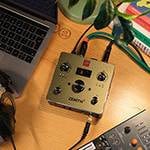
The reference circuit is the PMP E945.
It still has many fervent users, and once someone gets their hands on it, they rarely let it go, making it very scarce in the market.
Despite its excellent sound quality, I've hardly ever heard of anyone building it themselves.
There is a reason for this: it uses an AC 100V power supply, which makes it difficult to approach. However, considering that many professional musicians almost invariably own one and continue to use it actively, it is worth making one and keeping it at hand.
The most notable features of this buffer are its sound quality, thrust, and expansive dynamic range.
Imagine five sumo wrestlers, each weighing over 100 kg, pushing with all their might—that might give you an idea.
It has an incredibly wide dynamic range that won't flinch even with a substantial input signal.
Once you use it, you'll be hooked and won't want to go without it again.
This time, we have taken the core part of this E945, removed all unnecessary features like loops, and want you to purely experience the buffer.
Normally, a buffer doesn't have gain, but to compare with the original sound volume, we have made it possible to switch ON and OFF with a true bypass circuit.
Let's select the necessary components for this gain-equipped buffer.
The most troublesome component this time is the power supply.
Since we are using an AC 100V (wall socket) power supply, it is extremely dangerous. However, if you assemble each part carefully and check the wiring thoroughly, there's nothing to fear.
The reason why AC 100V is necessary is that we need a solid +15V and -15V dual power supply.
First, I want you to obtain this.
- Power transformer: 0-30V 100mA or 0-15V, 0-15V 100mA
(Since we are creating ±15V, considering the loss, a 0-18V, 0-18V transformer is also acceptable)"
I highly recommend the Sugano Transformer (S.E.L) SL-15130, but unfortunately, the company has gone out of business.
If you can't get it, you can use a transformer from TOYODEN, Toei Trans, Noguchi Trans, Hashimoto Trans, Swallow Electric, or Osaka KOHA. Just make sure to find a transformer that has a high-level balance between sound quality and performance.
It is rare to find a transformer that can maintain the specified voltage while carrying the specified current.
If you search diligently, you might miraculously find one.
A current value of 50mA to 100mA on both the positive and negative sides is sufficient. Any larger, and the transformer will just become bigger and heavier."
Schottky Diode
Nihon Inter 40V3A 31DQ04 ×4 pieces
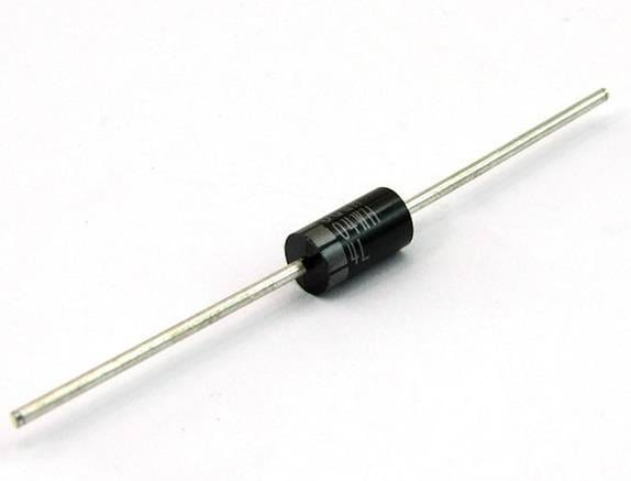
I also considered using an ultra-fast recovery diode, but it’s best to have the quickest possible response to instantaneous sounds.
Since this is not a vacuum tube circuit, we will use Schottky diodes without hesitation.
However, only use the Nihon Inter 31DQ04 or 31DQ06.
Three-terminal regulator:
JRC7815, JRC7915, one of each.
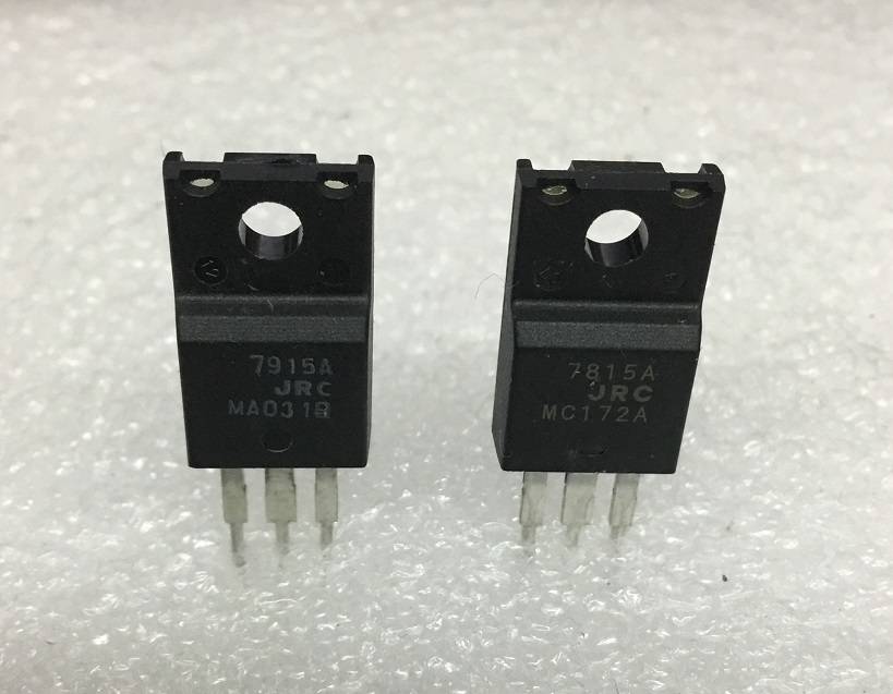
There is a reason for specifying JRC.
Of course, there is immense trust in their products, but JRC regulators can handle 1.5 times the current of those from other manufacturers.
While regular three-terminal regulators can only handle up to 1A, JRC guarantees up to 1.5A with the same size and specifications.
Since these parts tend to generate heat, this 1.5A capacity is significant. With this, a heat sink is not necessary for the current application.
Electrolytic capacitor
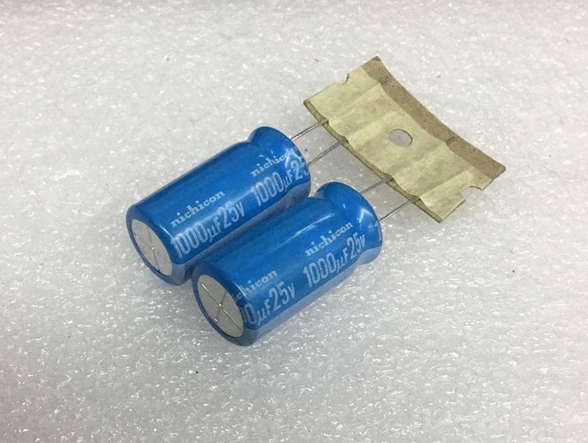
Capacitors:
- 1000uF/25V ×2
- 10uF/25V ×2
- 1uF/25V ×1
Choose the freshest Japanese-made products possible, such as from Nichicon, Rubycon, Panasonic, ELNA, TOWA, and SHOEI.
Multilayer Film Capacitor:
- Used for oscillation prevention in the three-terminal regulator.
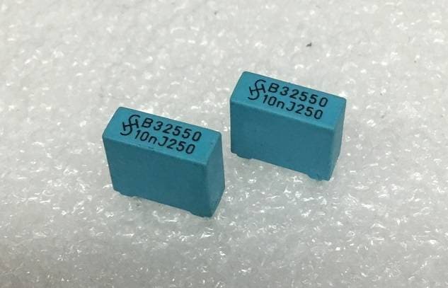
0.01uF/50V or higher ×2 pieces
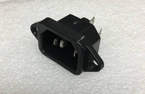
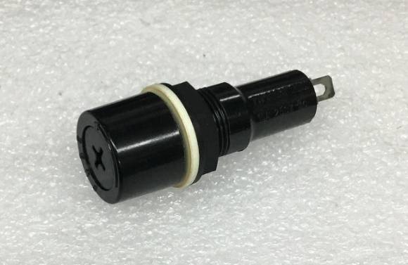
Additionally, one AC inlet and one fuse holder.
The fuse should be 250V 300mA midget slow-blow (time-lag) type, 1 piece.
These are the components needed for the power supply section.
Furthermore, I'll list all the components required for the circuit without holding back, so let's gather everything at once.
Capacitor used for the input section:
0.047uF ERO MKT-1813 ×1 piece
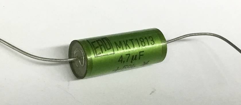
The MKT-1813 in the image is 4.7uF, but the required value this time is 0.047uF. Also, it can be yellow as long as it is MKT-1813.
Capacitor used for the output section:
1uF U-CON film capacitor ×1 piece
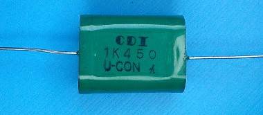
Although ERO has become quite easy to obtain recently, acquiring U-CON might be more troublesome.
However, since it's a simple circuit, cutting corners here will result in a significant difference in the sound output.
If it’s absolutely impossible to get them, then use vintage oil or paper capacitors for the input and film capacitors with a clear, open sound quality for the output.
Next is the single OP-AMP, which serves as the core component.。
Considering direct instrument input, the input impedance must be high.
Therefore, we have no choice but to select a FET input. Since there is only one circuit, we will go with the TL-071. However, to allow for easy replacement later, we will use an 8-pin IC socket.
Please be mindful of the resistors, just as we did last time.
I will use DALE RN-60D resistors again.

2.2MΩ ×1
100KΩ ×2
10KΩ ×1
4.7KΩ ×1
3.3KΩ ×2
330Ω ×1
Variable resistor 250KΩA-curve ×1
Additionally, this time we will include an LED so it can be used as an effect pedal. The footswitch will not only turn it ON and OFF, but also allow you to choose whether or not to pass through the gain control when it is ON.
Therefore, two footswitches are needed.
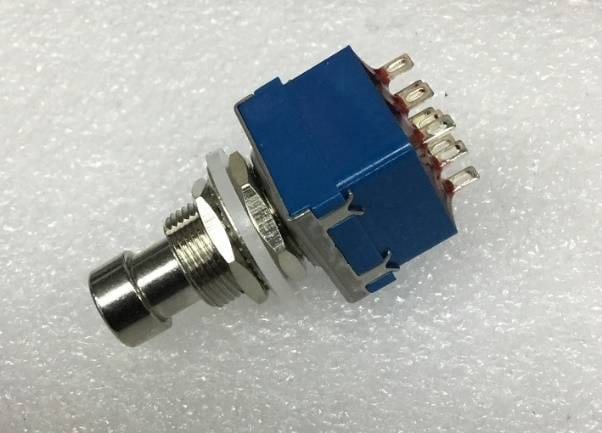
I would like you to obtain a 3PDT 9-pin alternate switch. However, since cheap ones often have contact issues, please try to get one with a good reputation.
Additionally:
Red LED 3mm ×1
Blue LED 3mm ×1
1N4148 ×4
8-pin socket ×1
Switchcraft 11 ×1
Switchcraft 12A ×1
Universal PCB 7cm × 10cm, 2 pieces
The case will be decided once all the components are gathered.
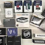
Apart from the capacitors, these items can likely be obtained around Akihabara or through online shopping.
This gain-equipped buffer is not available as a commercial product.
It's incomparable to effect pedals that operate on 9V or have internal voltage boosting.
Once completed, it's possible that a professional might come with a wad of cash asking to buy it from you.
Building circuits that require a power supply can indeed be a high hurdle for DIY, but once you overcome this power circuit, the benefits will be significant, as I will explain later.
For now, enjoy gathering the components.
Next time, I will explain the circuit and the assembly procedure. Stay tuned.


 第2弾 あなたのエフェクターボード見せてください
 【初心者向け】エフェクター講座
 あなたのエフェクターボード見せてください
 ベース用エフェクターの種類
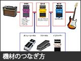 エフェクターのつなぎ方
 エフェクターの種類