Hello.
Lately I’ve been into eating gummies.
It all started when a coworker gave me some, and when I ate them… well, I’m more of a chocolate person, so when I first received them I thought in my head, “Hmm — gummies…”
I certainly wouldn’t buy them myself, and honestly, I can’t even remember the last time I ate some gummies.
By the way, the ones I was given were juice gummies that were mikan flavor — and Cororo in grape flavor.
So anyway, when I got home I tried the mikan juice gummy, and I was shocked.
It really tasted like a mikan.
So shocking, in fact, that I couldn’t help but mutter, “Wow!! That’s exactly mikan!!” out loud.
It’s hard to put into words, but the flavor felt natural, yet rich — it was simply mikan.
Of course, sweeteners and flavorings are in there — it is candy after all.
Still, the taste was so naturally done, it felt almost real, and that’s what made it good.
Next up was the Cororo grape.
This one was amazing too. When I first picked it up, I thought, “What is this? Some kind of membrane?”
But once I ate it — “Pop! Bouncy!!”
The texture seriously felt like I was eating an actual grape.
I was genuinely shocked that today’s gummies have evolved this much.
So lately, whenever I go shopping, I end up picking up a bag of some gummy I’ve never tried before.
I think everyone should eat gummies too!!
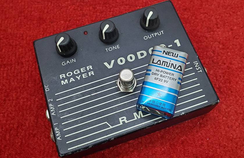
Alright, now let’s get to the main topic — starting from this post, I’d like to walk you through building the Roger Mayer VOODOO-1 over the course of a few entries.
Roger Mayer, as you probably know, is a well-established British effects brand, famous for pedals like the Octavia.
As for the VOODOO-1, it's a pedal that has undergone multiple spec changes since the early 1990s to adapt to the times, and it’s still widely used by guitarists today.
In terms of category, it’s somewhere between a fuzz and a distortion — I think it’s generally recognized as a pedal with quite a distinctive, quirky sound.
Also, the VOODOO-BASS is famously used by Seiji Kameda, which has made it pretty well known.
As for how I got to building it — a colleague of mine owns an early model of the VOODOO-1, and after borrowing one and playing around with it, I realized it was really my kind of sound, so I figured I’d try building one myself.
Now, the most important thing when making a DIY effects pedal is the circuit diagram.
I started searching for it online, comparing various versions, but I noticed several parts that didn’t quite match up.
Well, that kind of thing is pretty common in the DIY community.
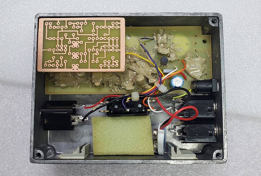
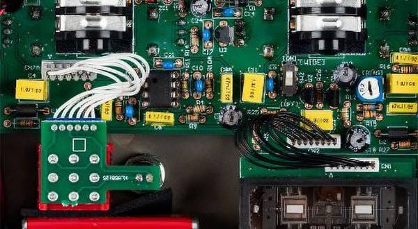
So, I asked my colleague if I could borrow the real thing and open it up to take a look inside…
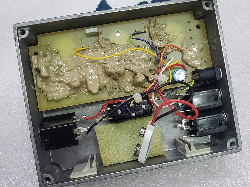
Sure enough, it was completely potted.
It was more solid than it looked, and it didn’t seem like it would come off easily with just a bit of effort.
Fortunately, it was a single-sided PCB, so I was able to check the trace pattern from the back and investigate the parts that caught my interest more or less by eye.
When I searched online, I found quite a few versions that weren’t potted, and it seems like there’s a wide variation in the types of components used, which probably has something to do with the year of manufacture or specific production runs.
What I was most curious about was the diode used for clipping, but I couldn’t figure it out clearly — so for now, I’ll just throw in a 1N4148 and experiment with other types later.
Also, circuit-wise, there are parts where you don’t necessarily have to stick to the original values (like the 2.2MΩ right at the input), so I’ll be making a few tweaks there.
At this point, some people might say, “Well, that’s not a VOODOO-1 anymore,” but… that’s DIY for you.
At least, that’s how I see it.
If you want the real deal, then buying the original pedal is definitely the surest way to be happy.
DIY is something different entirely; the fun lies in thinking it through, building it, and feeling that sense of accomplishment when it’s done.
So even though what I’m building will differ a little from the original, I’ll be approaching it with that DIY sense of accomplishment.
Also, tweaking it even more after it's finished is part of the fun too.
So, after investigating the circuit here and there, I modified the component layout based on a layout I found online, and here’s the pattern I created.
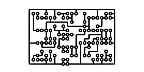
By the way, instead of the commonly used point-to-point wiring on a universal board often seen in DIY builds, this time I’ll be creating a printed circuit board (PCB) from a blank board and wiring the components that way.
The reason? Simply because I personally find it easier.
As for the pattern, it seems many DIYers design them with wider traces and smaller gaps to minimize the amount and time needed for etching solution. After trying a few things myself, I felt in the end that this layout works best for me.
Next, I printed the pattern onto a cutting sheet and applied it to the board here:
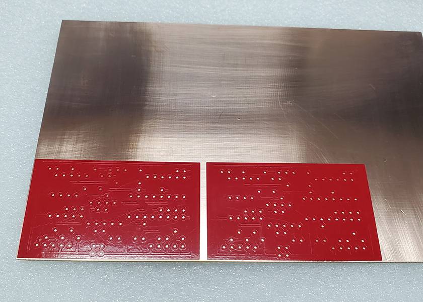
Then I trimmed the board into shape and removed the unnecessary parts of the pattern—here’s how it looks:
Now it’s starting to look a bit more like a real PCB.
Next, I’ll submerge this into an etching solution made from hydrogen peroxide + citric acid + salt.
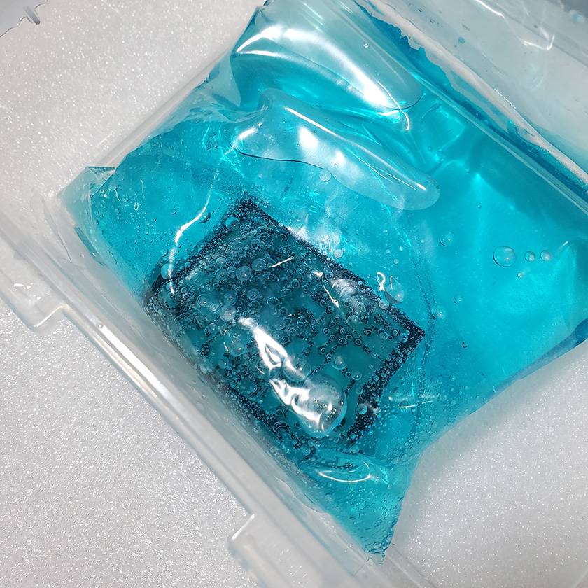
This will dissolve the copper in areas not covered by the sticker, leaving the pattern on the board.
This process is known as etching.
While doing this, it gives off a really nasty smell that’s probably hydrogen gas, so if you’re planning to try the same thing, make sure the area is very well ventilated.
Also, the etching solution must not be poured directly down the drain, as it can corrode metal and cause heavy metal contamination. Be sure to properly treat the waste liquid according to your local government’s disposal regulations, or entrust disposal to a certified waste management company.
As for me, after etching, I add aluminum foil to the solution to precipitate the copper, then filter it using a paper filter. The used aluminum foil is dried and thrown out with non-burnable trash, and the filtered liquid is checked to ensure it’s within a pH range of 5.8 to 8.6. Then, I dilute it with at least twice the amount of tap water before disposal.
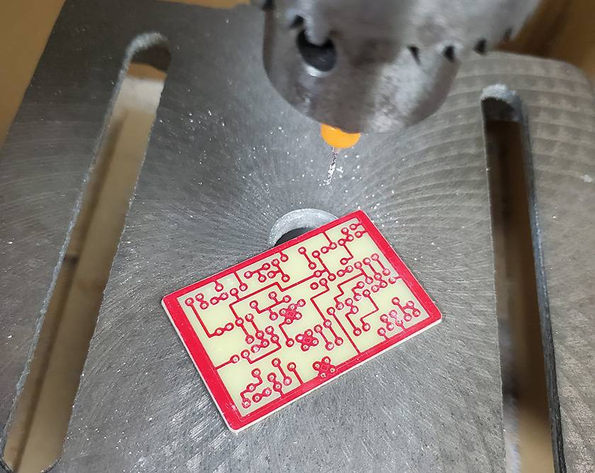
After the etching, I use a drill press to make holes in the board.
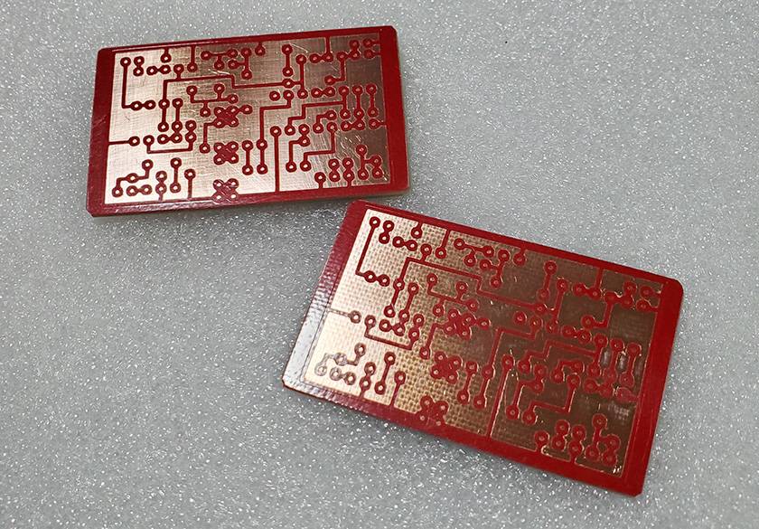
And once I peel off the sticker, clean the surface, apply flux and let it dry—the PCB is complete.
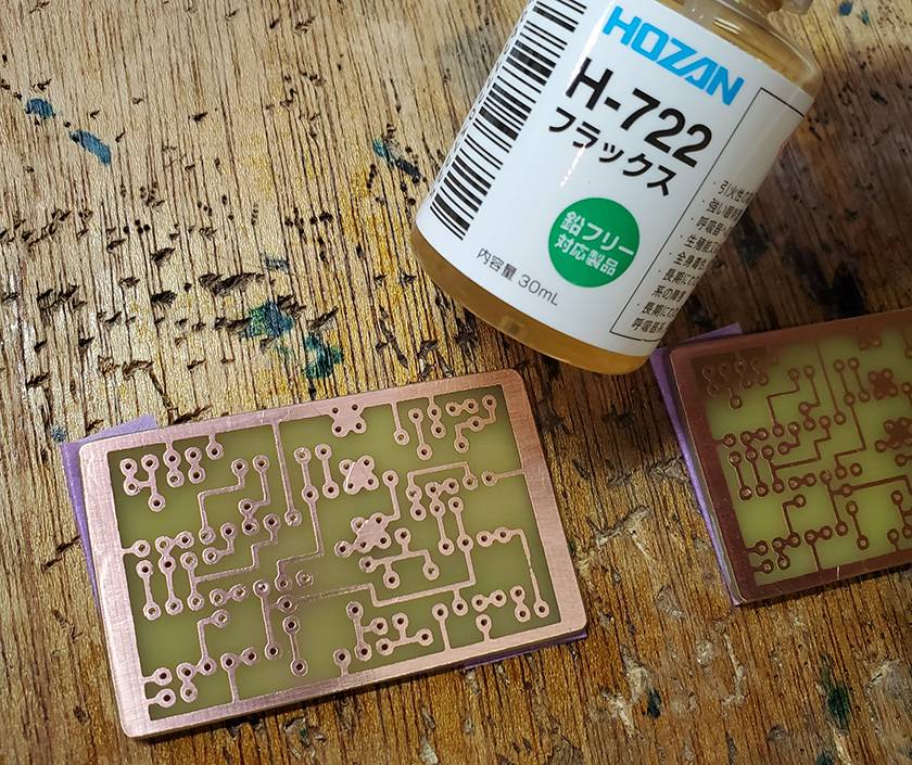
Here’s a comparison between the board I made this time and the actual one:
As you can see, there’s quite a difference in size.
Being able to make it more compact than the original is one of the appealing aspects of DIY, isn’t it?
So, how was it?
This time we only managed to finish making the PCB, so in the next post, I hope to move on to mounting the components and possibly modifying the case.
Also, when it comes to PCB creation, you don’t necessarily have to go through the hassle of etching like I did—these days, tabletop CNC machines are available at more affordable prices, and there are plenty of services that will fabricate PCBs for you, so using one of those is probably a better option overall.
I plan to go that route myself eventually.
Or at least get a proper PCB design software... but, well, I just can’t seem to get around to it.
And with that, I am wrapping up this entry. See you again on the Sound House Staff Blog. Goodbye!


![[Part 1] A High School Guitarist Wants to Build a Pedal - Circuit Board](/contents/uploads/thumbs/5/2024/2/20240228_5_25785_1.jpg)
 【初心者向け】エフェクター講座
 プレイテックのギターを最強に改造!!
 あなたのエフェクターボード見せてください
 配線カスタマイズ 第1回
 パーツの配線を知ろう
 お手入れに必要な道具