Reading back through my previous blog, I felt a lack of obsession... If I'm going to spend the time and money, shouldn't I strive to create a truly exceptional product? However, in these times, obtaining electronic components is difficult, not to mention finding vintage parts easily.
I want to share some incredible information with my passionate readers, but I can't announce it just yet.
Please wait a little longer.
Now, let me explain more about this buffer.
Some might wonder, "Do I even need a buffer?" or "How is it different from a DI?"
In my view, a DI's purpose is to lower impedance for accurate long-distance transmission of the original sound without actively altering the sound quality. Consequently, it doesn't increase the output beyond the original sound.
However, a buffer is closer to an effect pedal, allowing for more active sound creation. It lowers the impedance and can gain enough to beef up the output from the amp. The greatest advantage is that it significantly improves the response of any effects pedals connected afterwards, bringing a prominent presence to the instrument connected.
Above all, the drive feel you get with this buffer is something you can't experience without it, to the point where you wouldn't even need a compressor.
That's the reason many professionals continue to use it.
Particularly for bassists and acoustic-electric players who usually plug directly into an amp without using effects, it would be good to try this once.
The unique sound quality is likely to haunt your dreams.
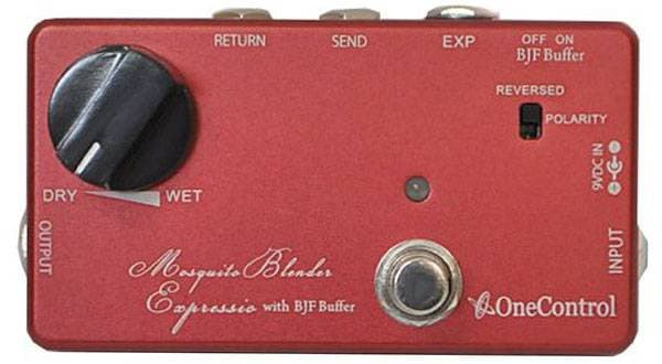
The buffer I'm creating this time connects guitars / basses directly and allows switching between true bypass live sound and buffered sound.
Additionally, when switched to buffered sound, a footswitch enables the choice between the original volume and a volume controlled by gain.
Your fragile live sound, vulnerable to noise assaults, will transform into a fully equipped Arnold Schwarzenegger just by passing through this buffer.
And it's capable of a gain boost. Imagine it like a towering Schwarzenegger charging forward with a shotgun or a machine gun (laughs).
However, since some people are attracted to a Schwarzenegger without heavy armor, merely shirtless, I thought it necessary to have a state where the signal passes through the buffer circuit without any gain change, only with reduced impedance. Therefore, I decided to add a footswitch to turn the gain on and off.
Circuit Description of the Power Supply
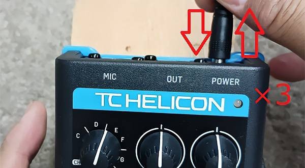
Since there is no power switch, the unit turns ON the moment it is plugged into an outlet.
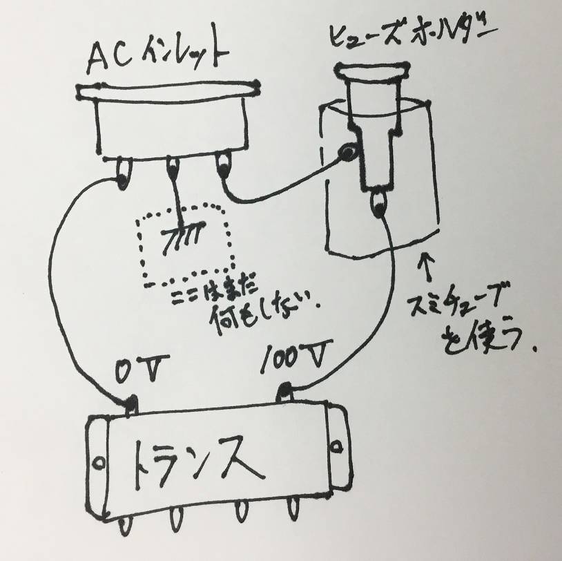
One side of the AC inlet is connected to the transformer input terminal marked 100V. The other side of the AC inlet is soldered to the side of the fuse holder. The terminal at the end of the fuse holder is then soldered to the 0V input terminal of the transformer.
**Important Note: Never touch the power supply or any parts while they are energized.**
Furthermore, for safety, it is advisable to insulate the soldered areas of the fuse holder and AC inlet with heat-shrink tubing.
Here is the wiring diagram for the power circuit.
Apologies for the messy handwriting once again, but please refer to it.
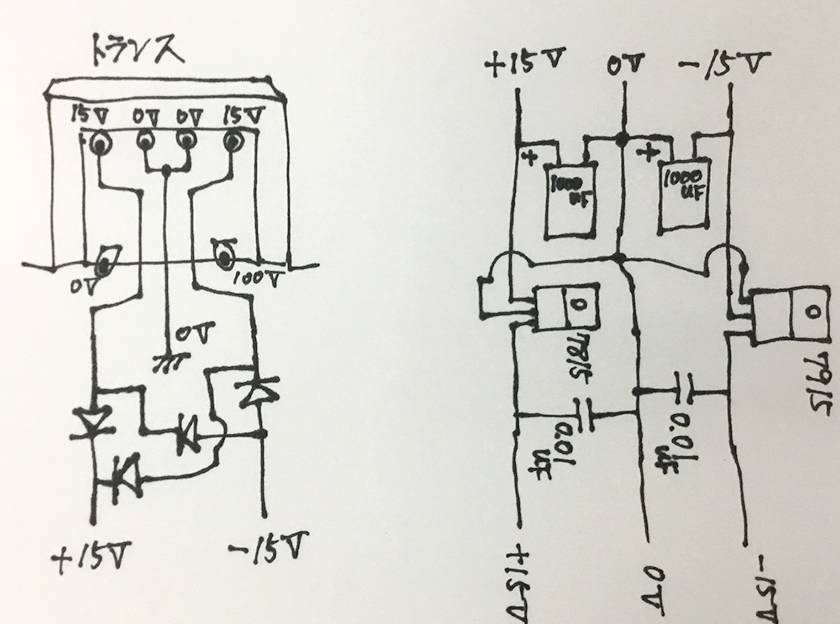
The secondary (output) of the transformer is not configured as 15V-0V, 0V-15V, but rather 15V-0V-15V or 0V-15V-30V. It’s all the same.
If the center is considered 0V, then each end will output AC 15V.
Please refer to the diagram below for understanding.

While passing AC 100V through a transformer changes the voltage from 100V to 15V, it remains AC (alternating current).
To convert this to DC (direct current), diodes must be used.
Have you understood this so far?
If not, please read this again until you can say, "I see!!!"
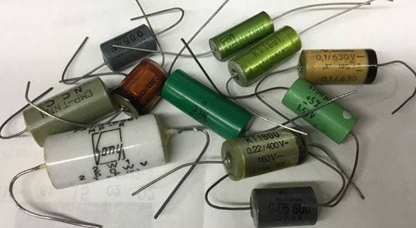
Once the current becomes direct current (DC) through the diodes, connect the electrolytic capacitors.
The capacity depends on the circuit's current consumption, but for this project, 1000uF is more than sufficient since we only need about 100mA for each positive and negative.
I typically use 1mA = 10uF.
Although the current has been converted to DC by the diodes, it is not yet stable, so we use a three-terminal regulator to smooth it out.
Note that the input parts of the 7815 and 7915 regulators are different.
Additionally, place a film capacitor right next to the regulator's output to prevent oscillation.
Without this, there could be significant high-frequency noise or susceptibility to electromagnetic interference from the surroundings.
Finally, the power supply circuit is complete.
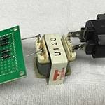
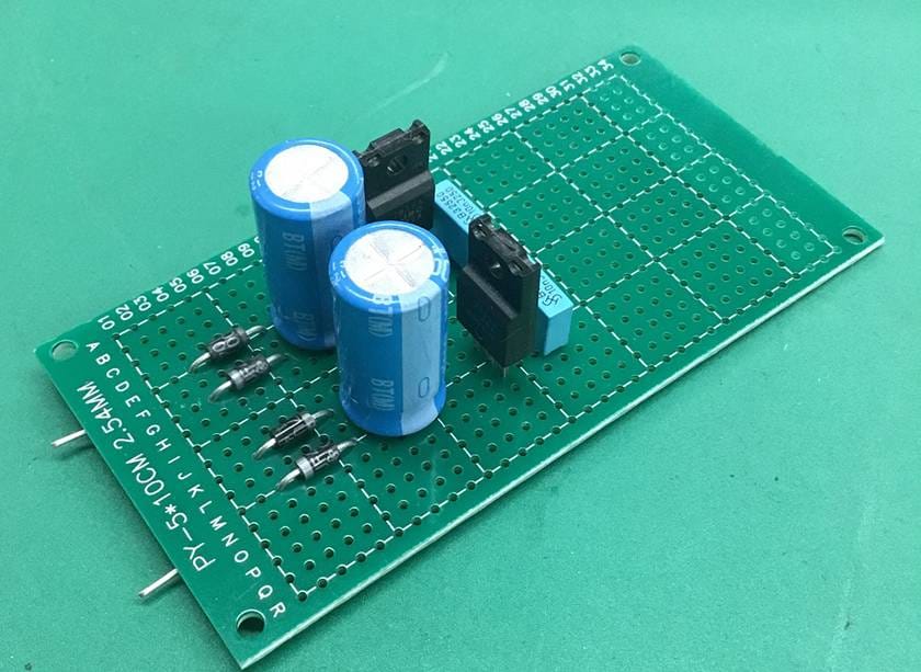
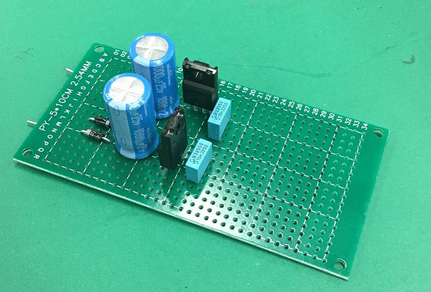
The entire circuit is planned to fit on the right half of the board shown in the image. The board size is 10cm x 5cm, with hole spacing of 2.54mm, using a phenolic single-sided universal board.
The original PMP E-945 operates a single OP-AMP at ±12V, but given the improvement in the quality of OP-AMPs and to further expand the dynamic range and increase the output signal's drive power, I deliberately chose ±15V.
In practice, there aren't many OP-AMPs that can fully swing up to the limit of their power supply voltage at ±12V.
Even with the LF351 used in the PMP E-945, applying ±12V only achieves a dynamic range of about ±9V.
I aim to maximize the performance of the OP-AMP by pushing it close to the limit of its supply voltage, allowing it to thrive with a dynamic range not achievable with commercial products.
I've explained the basics of the power circuit, and understanding this will be extremely useful when creating other devices.
In particular, it will aid in the design, construction, and even troubleshooting of effects units and amplifiers.
This concludes the explanation of the power section for now.
In the next installment, I will explain the buffer circuit and the wiring around the switches, including my original wiring designed to minimize switching noise (those unpleasant clicking sounds).
I have already confirmed that this has a tremendous effect on the true bypass switching of effects units.
Stay tuned for the next blog post.


 第2弾 あなたのエフェクターボード見せてください
 【初心者向け】エフェクター講座
 あなたのエフェクターボード見せてください
 ベース用エフェクターの種類
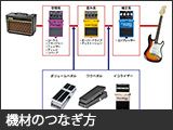 エフェクターのつなぎ方
 エフェクターの種類