One of the most convenient things to have when using a multi-effects pedal or multifunction digital effects pedal is a MIDI controller. If an effects pedal supports MIDI that can switch between banks and setting multiple parameters can be done instantly with a single switch. However, MIDI controllers for effects pedals are often expensive, and it is not easy to just try them out. Therefore, I would like to introduce a way to easily try MIDI control using that “something you have” at home.
#The main source of MIDI signals is UART
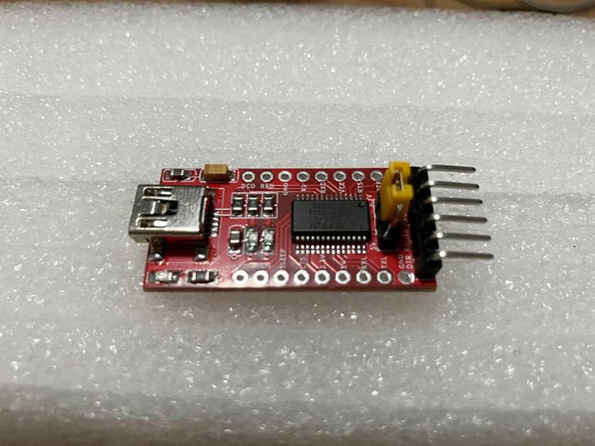
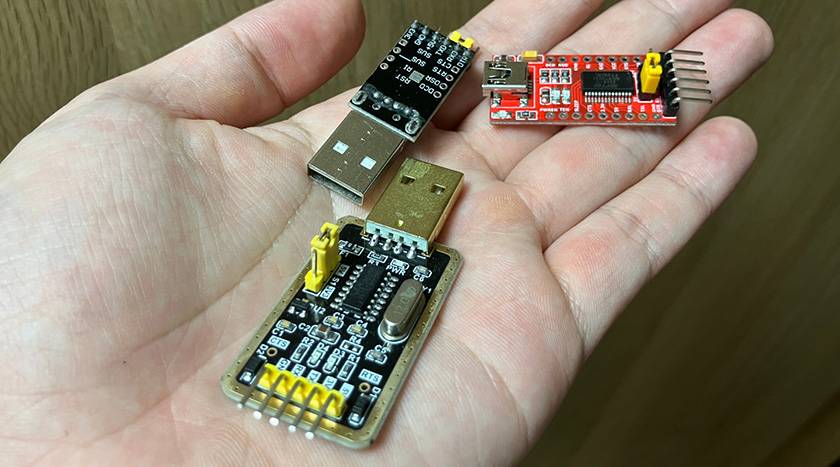
That “something” that allows you to easily experiment with MIDI control is, of course, a “USB-UART conversion board.
UART is a circuit frequently used for communication in microcomputers and it has a wide range of applications. In fact, MIDI data is sent and received over UART. If you check the “MIDI 1.0 Specification,” you will find that the MIDI send/receive circuit is a UART send/receive circuit with only one opto-isolator in between to avoid ground loops.
(The schematic also depicts a buffer circuit, but it’s not necessary for the USB-UART conversion boards available on the market, as they have sufficient drive capability.) In other words, you can easily control MIDI by simply connecting a 220Ω resistor to your USB-UART conversion board and connecting it directly to the effects pedal’s MIDI IN.
#What kind of data should I send?
Now that we know that a USB-UART conversion board and two resistors are all we need to send MIDI, what kind of data can we send to control effects pedals? PC (Program Change) and CC (Control Change) are mainly used for MIDI control of effects, but data sent via UART is usually a string of characters or bytes and there is no such distinction between CC and PC. Therefore, it is necessary to read what the standard is in order to find out what kind of data is used to express control commands such as CC and PC.
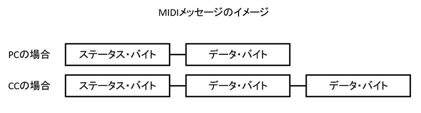
MIDI control instructions are called “messages,” and each message consists of one “status byte” and zero or more “data bytes”. The status byte specifies the action of the PC or CC, and the data byte specifies a numerical value. For example, Line 6's HX Stomp can be set to bypass CC's 70 with 0. The CC part of the MIDI control here is specified by the status byte, while 70 and 0 are specified by the data byte. The status byte and data byte are both one byte of data, as indicated by their names.

The structure of the status byte is that the first bit (MSB) is fixed at 1, the following three bits specify the type of operation, and the remaining four bits represent the MIDI channel. The reason the first bit is fixed at 1 is to distinguish it from the data byte whose first bit is fixed to 0. The correspondence between the second through fourth 3-bit combinations and the operation is shown in the figure above, 0b011 for CC and 0b100 for PC. The trailing four bits represent “MIDI channel-1,” minus 1 because MIDI channels are numbers from 1 to 16, whereas the numbers that can be represented by 4-bit binary numbers are 0 to 15, with one off. The structure of the data byte is simple: the first bit is fixed at 0 and the remaining 7 bits specify the numeric value. The reason why the data byte is one byte even though the MIDI PC and CC can only specify numbers from 0 to 127, or 7 bits is the first byte that’s used to identify the data byte.
#Test on an actual device
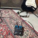
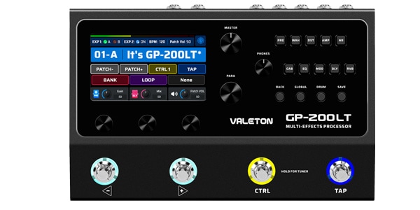
Now, let's test whether MIDI control is really possible with a USB-UART converter board on an actual device. The equipment used for the test is a multi-effects pedal called GP200-LT from Valeton.
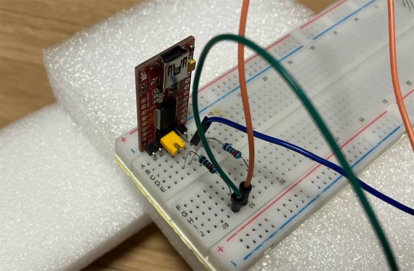
First, a USB-UART conversion board and two 220Ω resistors are placed on a breadboard. Connect the resistors to the TX and VCC pins of the board.
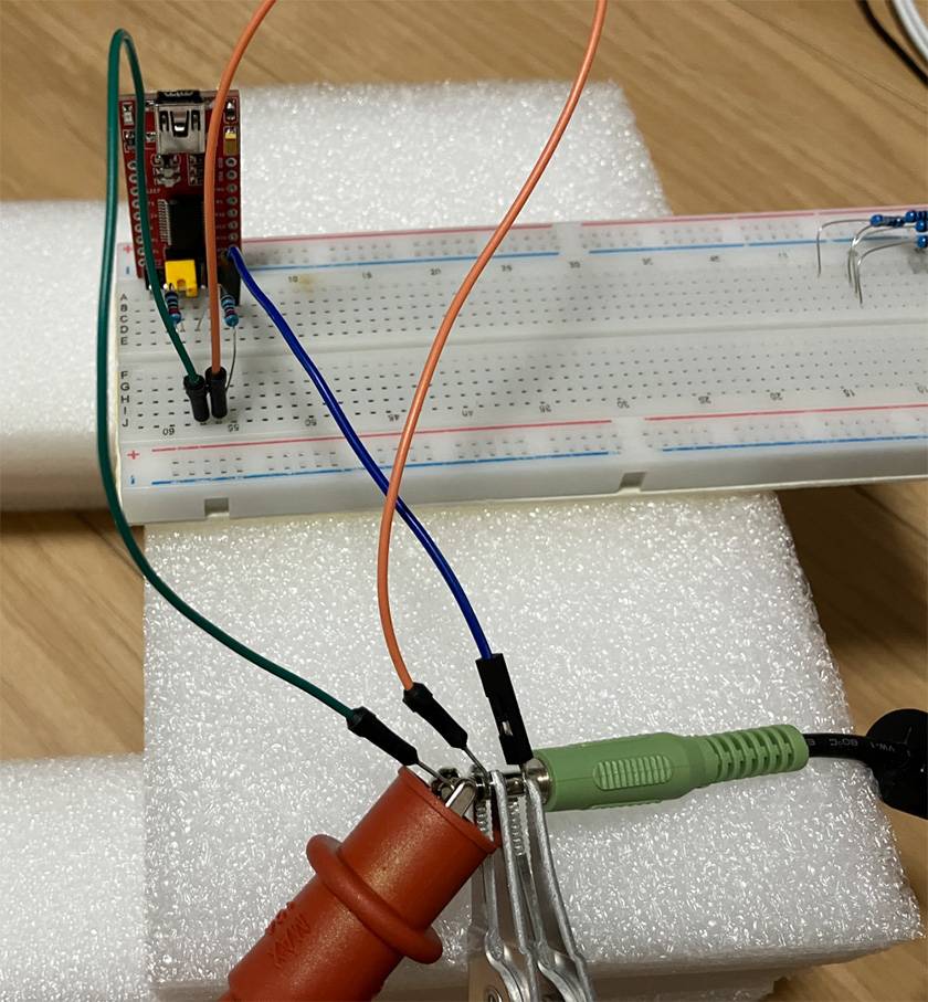
The MIDI input terminal on the GP200-LT is a 3.5mm jack, so prepare an appropriate stereo audio cable and wire it up. Wiring the MIDI signal to the 3-terminal plug is described in the link as “3-Terminal Plug - MIDI (English version)”. Pin 5 is the tip, pin 4 is the ring, and pin 2 is the sleeve.
If you check the MIDI schematic that’s shown earlier, you can confirm that pins 5, 4, and 2 lead to UART TX, VCC, and GND, respectively, so wire them as shown. Since this is a test, the end of the Dupont wire is clipped to the plug, although it is a little unstable.
Connect the other end of the audio cable to the MIDI input of the GP200-LT, and connect the USB-UART conversion board to the PC with a USB cable, and the hardware is ready. Next, start up the tool for sending data from UART. There are various tools available to communicate via UART from a PC, but this time I will use Python and pyserial.
import serial
s = serial.Serial('COM3', 31250) # Change the port name as appropriate.
s.write([]) # The data to be written will be placed inside the parentheses.
s.close()
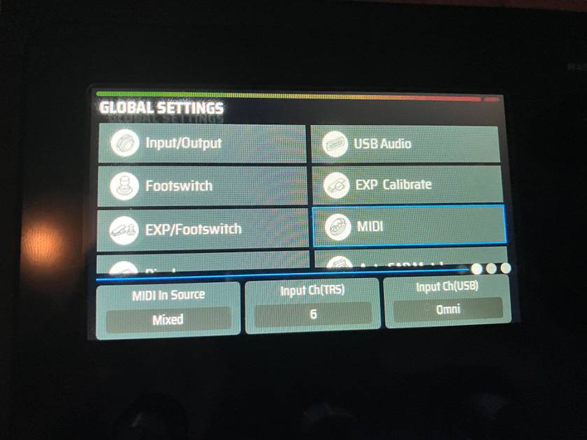
The MIDI standard document also includes specifications for start and stop bits, but these settings are the same as the default settings, so there is no need to change them separately. Only the communication baud rate needs to be set to 31.25 kbps, which is the MIDI specification. The data to be sent is determined by consulting the GP200-LT user manual. The user manual, which can be downloaded from the manufacturer's website, has a MIDI control data correspondence table on pages 52-53.
Since I want to try both CC and PC, I will try “DST Module on/off” (CC#49) and “BANK MSB” control (CC#0).
The status byte of the MIDI message for “DST Module on/off” is 1 at the beginning, and the following 3 bits are 011 for control change, and the MIDI channel is 6-1 = 5 = 0b0101 since the input channel is set to 6 on the main unit. To sum it all up, the status byte is 0b10110101.
The first data byte following is CC number 49, and the second data byte can be any value from to 63 to disable distortion or 64 to 127 to enable it. In the test, 0 is used for disabling and 127 for enabling. In summary, we can send [0b10110101, 49, 0] to disable distortion and [0b10110101, 49, 127] to enable distortion. You can see in the video below how sending these data turns on and off the distortion block of the effector.
Next, I will discuss bank switching using the GP200-LT's PC (Program Change). According to the manual's correspondence table, CC#0 must first be sent to switch banks. The manual states that if the second data byte of CC#0 is 1, the bank is switched from 01-A to 32-D, and if 0, from 33-A to 64-D. However, when I actually tried it, I confirmed that it is the opposite and when 0, the bank is switched from 01-A to 32-D.
This time, I will test switching from another appropriate bank to the 9-C bank. Bank switching is performed by PC control, but CC control must be performed first; send [0b10110101, 0, 0] to designate bank switching for CC#0. Here, 0b10110101 is a status byte indicating “CC control to channel 6,” followed by two zeros indicating “bank switching mode from 01-A to 32-D.” PC control data is then transmitted.
The PC control status byte is 0b11000101 since the first bit is 1, the operation bit is 100, and the channel is 6. The data byte must be calculated based on the bank number. The data byte for bank number 9-C can be done by counting from 0, or it can be found by the following procedure.
The alphabetic part of the GP200-LT bank is A to D, so this part corresponds to the lower 2 bits of the data byte, and the numeric part corresponds to the upper 5 bits. The integers that can be represented by the upper 5 bits are 0 to 31, and the numbers in the banks are 1 to 32, so the value obtained by subtracting 1 from the number in the bank is the upper 5 bits. Since the alphabetic part represents 10-13 in hexadecimal and the lower 2 bits can be obtained by subtracting 10 from the alphabet as it is in hexadecimal. Therefore, the data byte to select bank 9-C can be obtained by [((9-1)<<2) + 0xc - 10], which is 34.
To summarize, to switch the bank to 9-C by PC, I can send it as [0b11000101, 34]. The latter part of the video shows how the bank is switched by sending these CC and PC control commands in succession.
#For 3.3V boards
After reading this far, you may be thinking, “I want to try this, but I only have a 3.3V type board and I can't get a 5V signal!” You can put a level shifter between the 3.3V UART and the resistor, but there is another way. In fact, MIDI has a standard for 3.3V, and the details are described on page 2 of the linked “MIDI 1.0 Electrical Specification Revision (Japanese version).” When using the 3.3V system, the resistor connected to VCC should be 33Ω and the resistor connected to TX should be 10Ω, although we do not have a verification video, I tried a combination of a 10Ω resistor and three 100Ω resistors, and was able to control the effects pedal even with a 3.3V signal.
#Practicality is the matter
MIDI control may seem like a difficult task, but I hope you now understand that it can be achieved easily and at low cost by using a USB-UART conversion board that can be found in every house. However, even though it can be controlled with a PC, it is not practical to put a laptop next to the guitar and step on the keyboard with your foot while playing. The issue remains that it is meaningless if you cannot use it while playing. In other words, a home-made MIDI controller is feasible if there is a device that is not as bulky as a PC and allows free UART communication. Currently, I am still in the research stage, but if I am able to have a more concrete plan, I would like to share it again with Sound House again. Thank you for reading this far.
The column “sound & person” is made possible by your contributions.
For more information about submissions, click here.


![[2025 Latest Version] 8 Recommended Reverb Effects Pedals!](/contents/uploads/thumbs/2/2023/8/20230801_2_23473_1.jpg)
 BOSS MIDIケーブルで広がるパフォーマンスの世界
 【初心者向け】エフェクター講座
 あなたのエフェクターボード見せてください
 ベース用エフェクターの種類
 エフェクターのつなぎ方
 エフェクターの種類