Once again, without even improving my own power supply, I ended up making one myself. The trigger for this was a certain musician who recently came to me, insisting that this sort of thing is absolutely necessary, so please make it somehow!! I tried making it, but I was blown away by how convenient it was and how good the sound turned out.
To all the readers who use effects pedalboards, and to those who own multiple guitars or amps, I definitely want you to make this for yourself too, so I decided to write about it this time.
A "buffered splitter" is a device that splits one signal into two.
However, if you split a guitar or bass signal without any consideration, you end up with miserable results due to sound quality deterioration and volume drop.
Therefore, you give each split signal a high-performance buffer that prevents any loss in sound quality or volume.
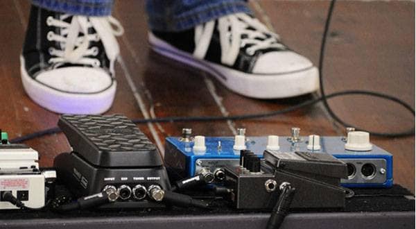
The musician who asked me to make this is a hardcore player who uses two amp heads simultaneously, and insisted on feeding both amps without any volume loss.
After completing it and checking the sound quality and volume, I thought, “Can such a good-sounding splitter really be made this easily?!” I even considered making it a product, but it was too much trouble, so I decided to just share it here.
It’s a discrete circuit using only one FET without any OP-AMPs, so noise is minimal, the circuit is simple, and it requires few parts. Anyone experienced should be able to finish it quickly.
Now then, here is this month’s one-off DIY: let’s make a Buffered Splitter.
First, the materials (this time, general-purpose parts are perfectly fine, so no need to be particular about brands)
- Aluminum or metal case×1
- DC jack×1
- Mono phone jack×3
- Perforated board×1
- 1/4W resistor 1MΩ×2
- 1/4W resistor 3.3KΩ×2
- Film capacitor 0.22µF / 50V or higher×2
- Electrolytic capacitor 10µF / 16V or higher (NP or BP type) ×2
- FET (choose any two from 2SK30A / 2SK369 / 2SK117 / 2SK170)×2
- Wiring wire AWG24–20, about 1 meter is enough
These materials are sufficient.
Normally I would be very particular about the parts, but this time anything will do.
However, the jacks used at the connection points are critical for whether sound comes out or not, so if possible, please purchase these specifically.
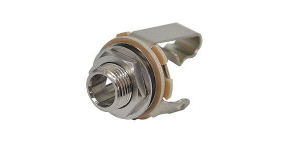
Even if you manage to build the circuit properly, it’s no fun if the crucial jack connections are bad and no sound comes out.
Now, here is the usual charming hand-drawn circuit diagram.
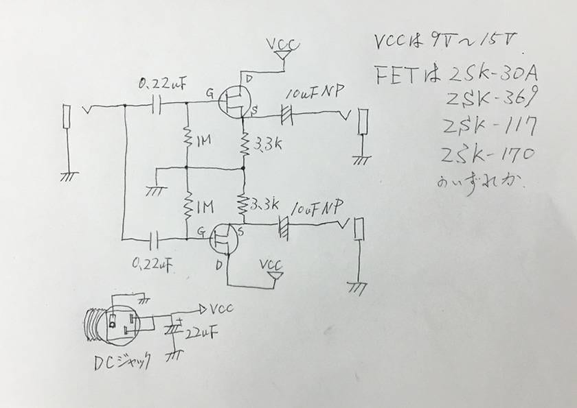
When you input the signal into the jack on the left side of the circuit diagram, the signal is first split into two, and each passes through a separate buffer before outputting.
The key component is the FET.
Although most of these are now discontinued, you should still be able to find some with a search.
This time, the power supply will be only an AC/DC adapter (center minus, 21 mm, 9V to 15V).
Now, let’s move on to the assembly process.
For the case, I recommend an aluminum case with the model number YM-100 for its perfect size.
It’s just the right size and, above all, easy to work on (and also wallet-friendly).
Its durability is not great, but since this does not have a footswitch, it won’t be stepped on hard.
The size is 100mm × 30mm × 70mm.
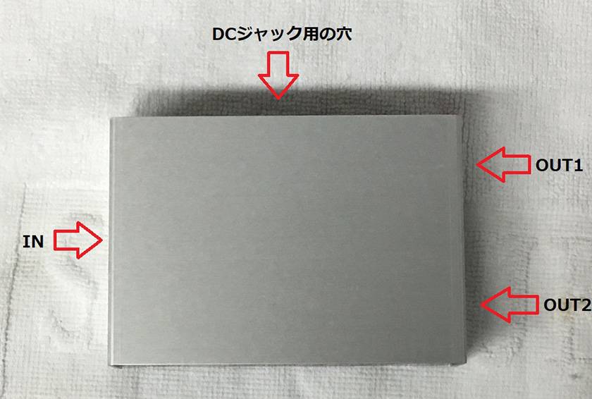
Once you drill four 12mm diameter holes in it, the case work is complete.
■ Image showing the relative positions of holes on the case
And here’s a special bonus:
I’m including a layout diagram that shows the parts mounted on the perforated board and also the wiring.
The board size of 40mm × 45mm is sufficient.
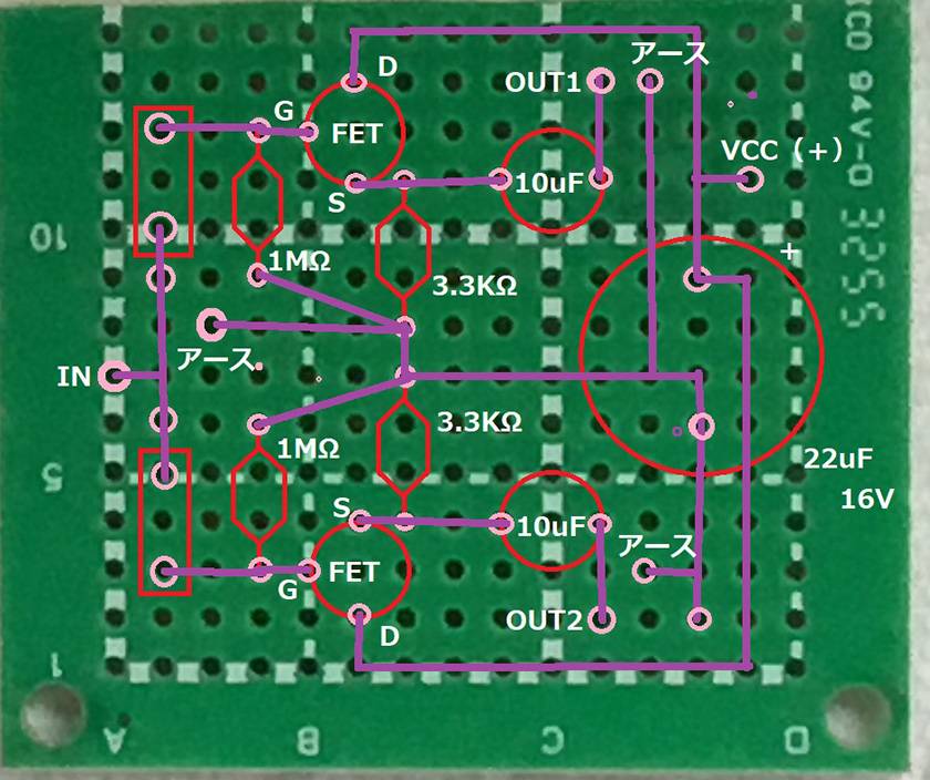
- Red lines indicate the outlines of parts
- Purple lines show the wiring pattern
- White text indicates the part names
- Be sure to carefully check the pin configuration of the FET you use against the datasheet. If you mix them up, no sound will come out.
After that, just assemble it and you’re done.
Once you understand when and how to use this device, you’ll soon want a second one.
I chose FETs that are relatively low-noise and highly regarded for sound quality, but if you have a device you prefer, that’s totally fine.
Any N-channel junction FET (J-FET) that can be used at 15V or higher will work.
Please give DIY a try first.
Thus concludes this first one-shot DIY buffered splitter (1) successfully. Come back to read more in the next post!


 ギターパーツの沼
 【初心者向け】エフェクター講座
 DIY ギターメンテナンス
 プレイテックのギターを最強に改造!!
 ギターアンプ スタックタイプ編
 エフェクターの種類