Thank you for your patience, here is the long-awaited buffer circuit section.
But before that, let me share the "extraordinary information" I mentioned in the previous blog.
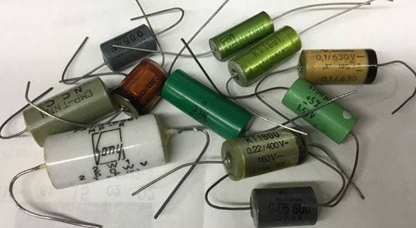
I'd like to introduce a site that sells rare components (mainly capacitors and other parts) that appear in my DIY articles.
If you enter "capacitor" in the site's search banner, it will come up right away.
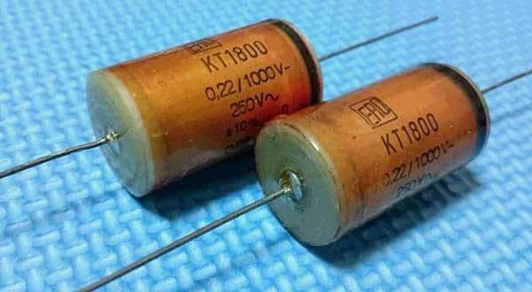
Limited in quantity, they sell various capacitors and rare components.
These are difficult to find and often impossible to acquire, but SOUND MART has obtained them through unique channels.
These components are used not only in my production articles but also in general for effects units and high-end audio equipment.
If you find something good, I recommend buying it without hesitation.
They offer items that are hard to find at other stores at reasonable prices and in abundance.
I would be very happy if everyone could share them amicably and reach many people.
Acquiring good parts really boosts your motivation to create! No doubt about it.
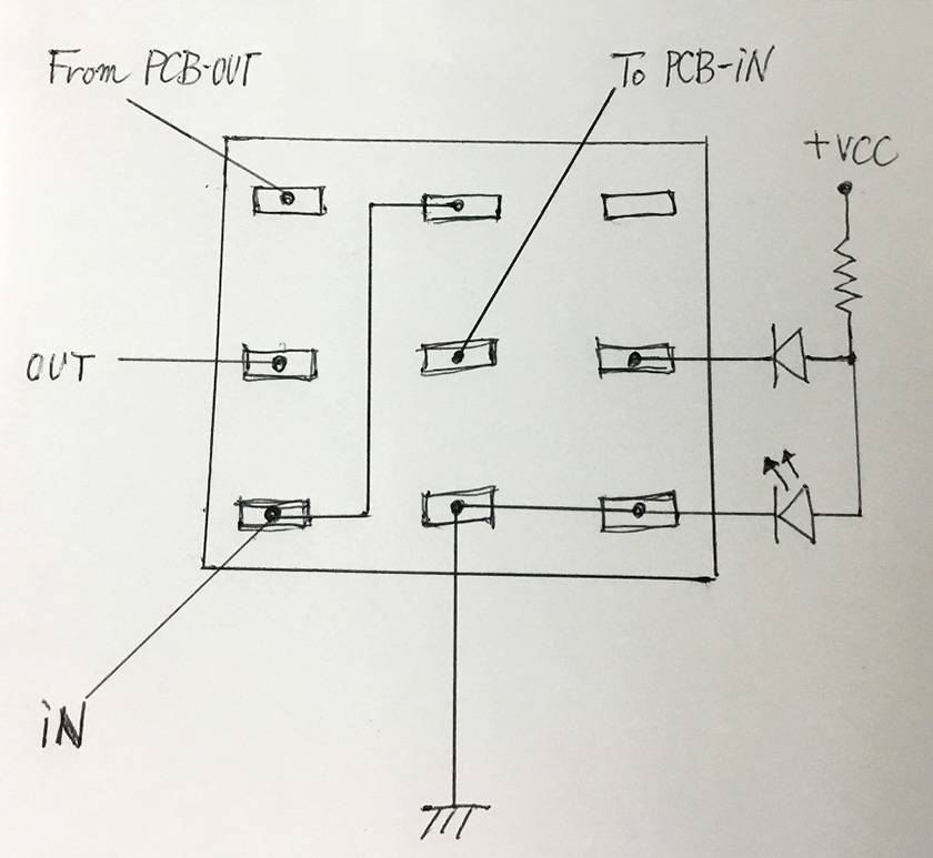
Now, this time, I'll introduce the buffer circuit itself, the wiring around the switch, and the true bypass wiring to minimize switching noise.
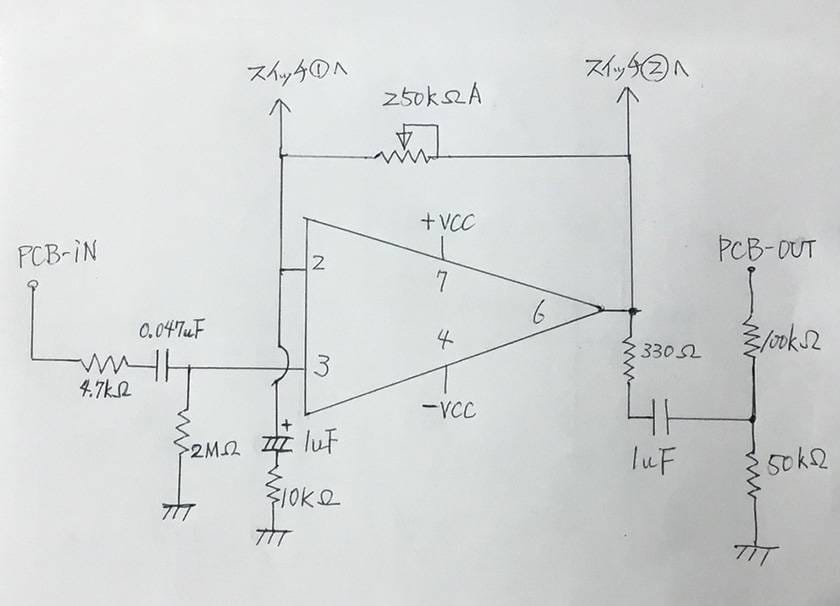
Now, let me introduce the buffer circuit with my usual handwritten diagrams!
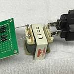
In this circuit, particular attention must be paid to how well you can wire the 8-pin socket using a universal board (perforated board).
Though it is quite challenging, please work slowly and carefully, ensuring that neighboring pins do not short-circuit by using the minimal amount of solder.
The switch connected to pins 2 and 6 of the operational amplifier is a simple on-off switch, but the wiring is arranged to light up an LED. Make sure not to make any mistakes.
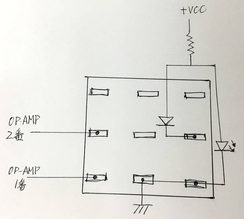
Here is the wiring for the gain ON-OFF switch.
Additionally, I'll include the wiring for the buffer ON-OFF switch as well.
* A 1/4W resistor is sufficient, but if VCC is 9V, a value between 2KΩ and 4.7KΩ is recommended.
* A 1N4148 diode is suitable for use in parallel with the LED.
This wiring significantly reduces the highly unpleasant switching noise, the "pop!!!" sound, that occurs during true bypass switching, bringing it down to a level that is unnoticeable during use.
To be honest, I want to say, "There is no noise at all!" However, there are people out there who, without building it, irresponsibly claim, "That's wrong" or "That's incorrect," without even verifying. Therefore, I have modestly expressed that the circuit reduces noise to a level that is unnoticeable during use.
*There is no commercially available product (domestic or international) that uses this exact circuit.
This is a completely original circuit that I have designed.
Feel free to use it as much as you like, but please contact me if a manufacturer plans to incorporate it into a product or if it is to be used for commercial purposes.*
Let me explain briefly why this circuit suppresses noise.
What is the cause of that noise in the first place?
I thought it was the LED. In fact, when I made an effects pedal, the noise wasn't noticeable with just the ON-OFF switch, but as soon as I put it in the case and attached the LED for the ON state, it started making noise.
So, I thought, why not completely separate the circuit and the LED? However, it’s impossible to separate the power supply for the LED from the circuit's power supply.
I figured out that the current flowing to the LED when turned on was causing the problem, but the issue was what to do next.
At that moment, a 100W incandescent bulb above my head lit up brightly.
Maybe the idea of passing current through the LED when the effect is turned on is wrong?
I came up with a reverse idea: keeping the LED lit and stopping the current flow only when the effect is turned off.
With this approach, noise should occur when the contacts inside the switch make contact while turning the effect off.
However, at that time, it's in true bypass mode, so no matter how much noise enters the effect sound, it won't come out of the output. Conversely, when turning the effect on, the contacts inside the switch gently separate, so no noise is produced.
The final problem is how to reverse the LED lighting operation.
In other words, the LED should be off when the switch contacts are touching, and on when the switch is open.
To achieve this, I connected a diode in parallel to the negative side of the always-on LED.
When this diode is grounded (shorted to earth), the LED turns off.
But wouldn't this make the power consumption infinite? No, it doesn't.
The voltage drop across the diode is 0.6V, which hardly affects the power consumption.
When the diode is disconnected from the ground, current flows through the LED, causing it to light up.
While a potential difference is also a cause of noise, if the ground from the input to the output, and even to the power supply, is a common ground, you don't have to worry about noise caused by the potential difference. However, it’s a different story if you have isolated the circuit's ground from 0V using resistors or capacitors.
It's okay if you don't understand the content of the above discussion.
Of course, it would be better if you did, but even if you don't, you can still wire the low-noise switch system.
This time, we'll end at the point where we drill holes in the chassis and wire around the switches.
Purchase the rare parts and wait eagerly for the next blog.
The next installment will conclude the buffer series!!! Stay tuned.
P.S.
After reading the previous DI series, I received emails from those who diligently searched for parts and completed their builds.They reported that the sound quality was astonishing compared to the manufactured products they had been using.
Thank you very much. I am truly delighted.
While I cannot respond to each person individually, I would like to take this opportunity to express my gratitude.


![The Road to Your Complete DIY Equipment: 2nd Edition: The Illusive Vintage Sound! Amplified Buffer Get your hands on the legendary device exclusively used by professionals [Parts]](/contents/uploads/thumbs/2/2023/3/20230303_2_21537_1.jpg)


 配線カスタマイズ 第1回
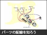 パーツの配線を知ろう
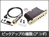 ピックアップの種類(アコースティックギター)
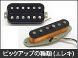 ピックアップの種類(エレキギター)
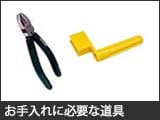 お手入れに必要な道具
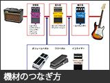 エフェクターのつなぎ方