Hello,
I’ve recently gotten hooked on Space Cobra.
Recommended by my junior colleague, I’ve been watching this classic anime.
Cobra, the protagonist, is tough, stylish, full of humor, and just a bit vulnerable to women—a quintessential man among men. However, I couldn’t help but laugh when his cigar suddenly turned into a light or an oxygen tank without any explanation.
Also, the opening theme song by Yoko Maeno is incredibly cool!
Its catchy bass line is truly captivating, so I highly recommend giving it a listen.
Now, let’s move on to soldering potentiometers.
However, there are various ‘schools of thought’ in this field...
The methods differ quite a bit depending on the manufacturer or repair technician. Therefore, I’ll explain the wiring method for volume control based on my usual approach.
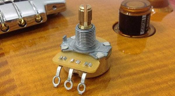
*I’ll be using an unknown potentiometer found in my parts box.
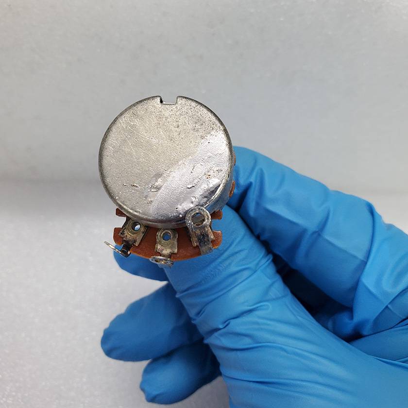
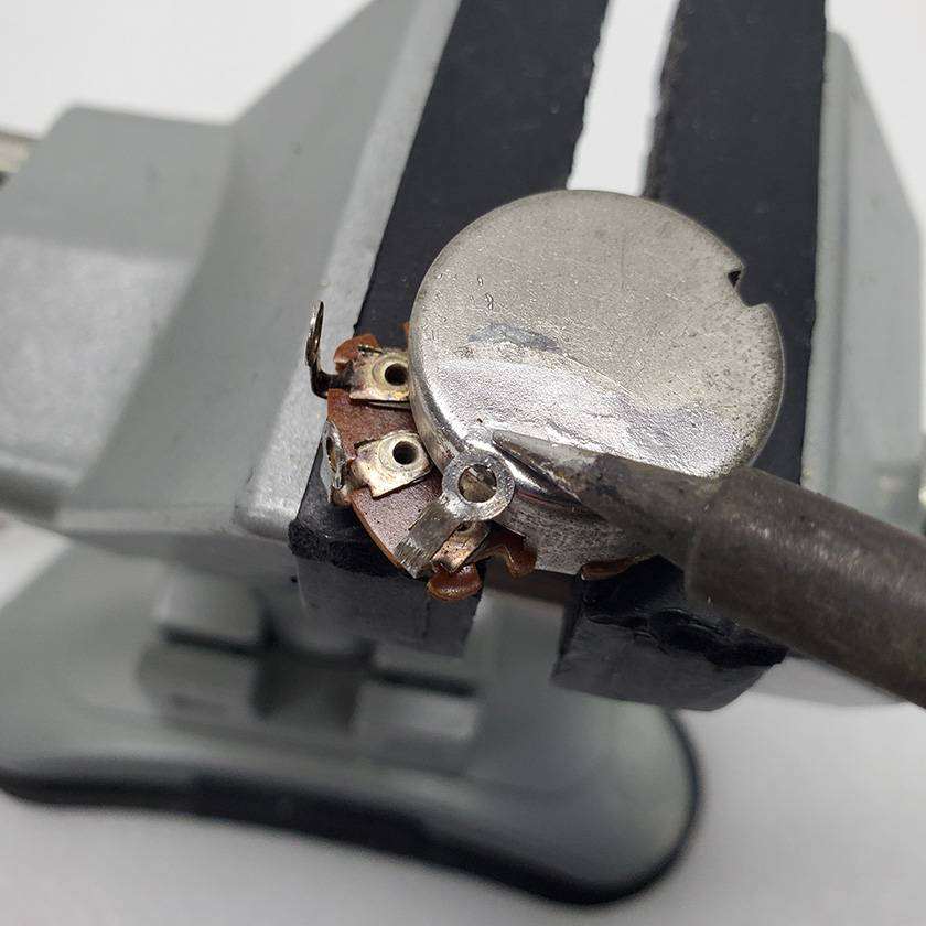
◯ Securing the Potentiometer
First, securely fix the potentiometer onto some sort of base.
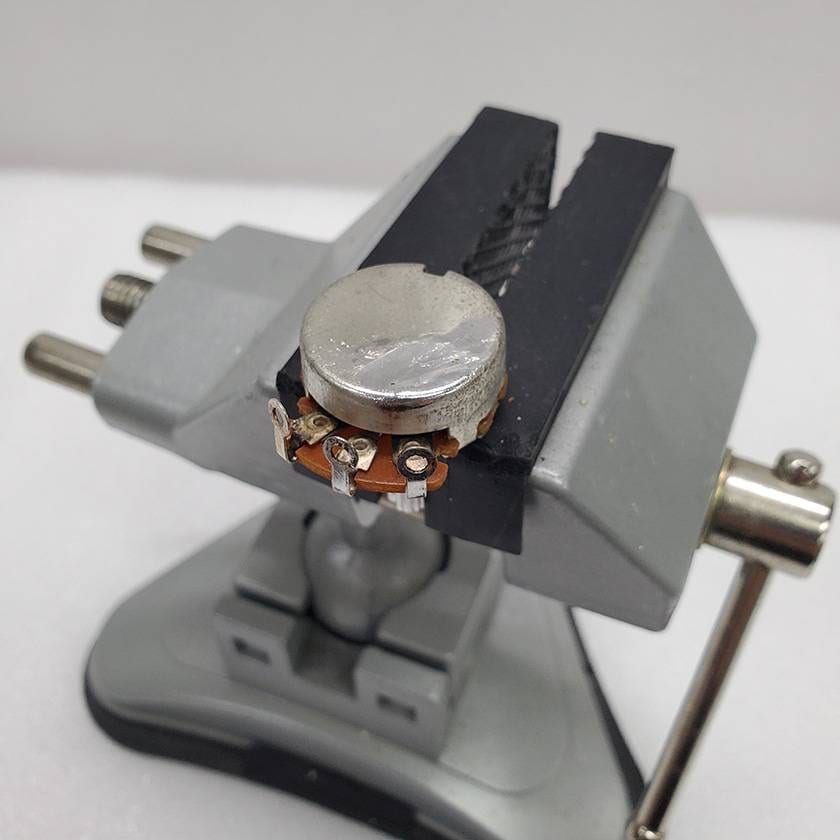
This time, I’ve clamped the potentiometer, but you can use MDF scraps, a pickguard, or even sturdy cardboard with holes, as long as it’s securely fastened.
What’s important is securing it firmly, not necessarily the object used.
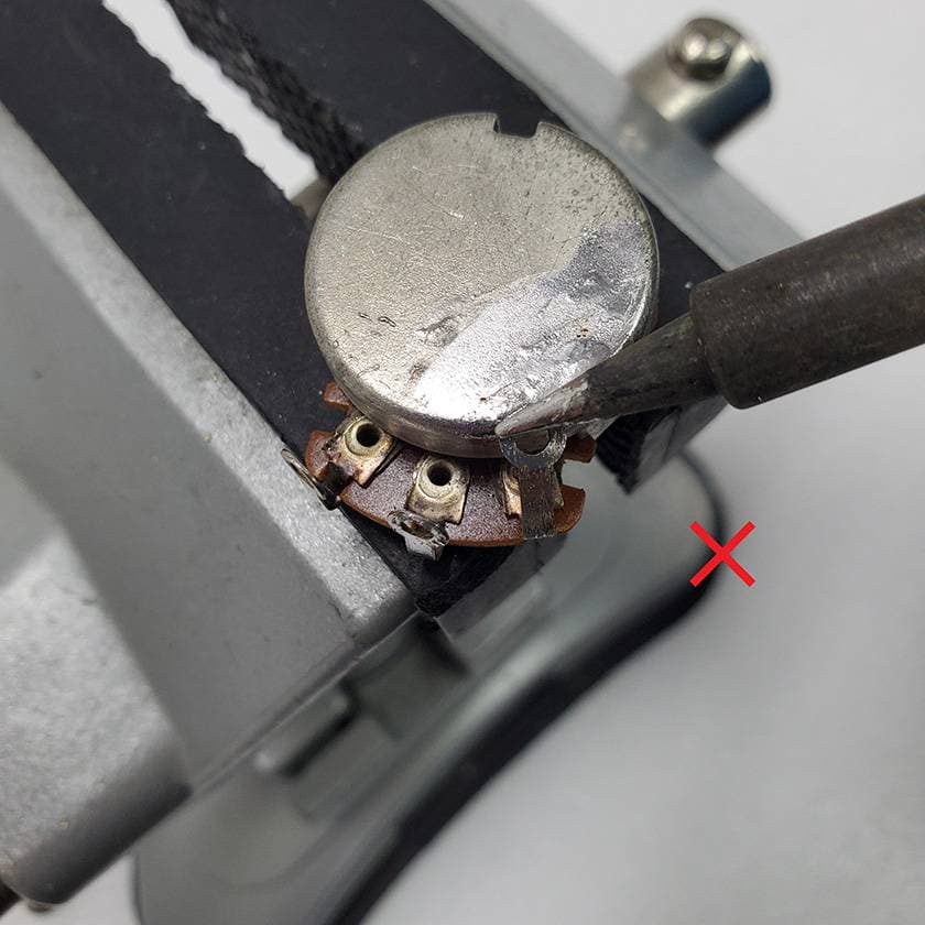
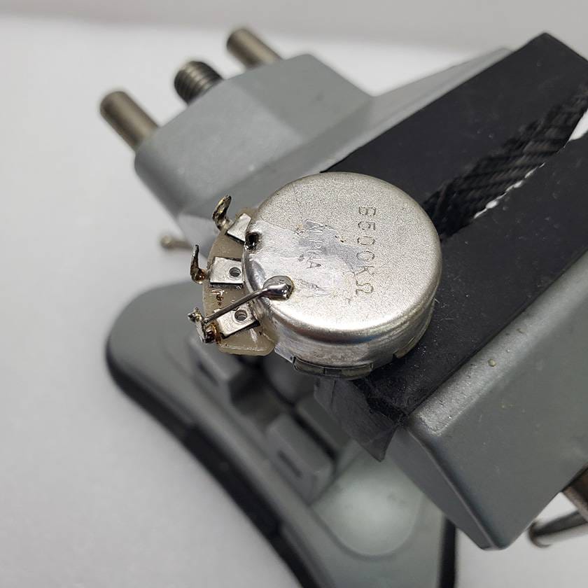
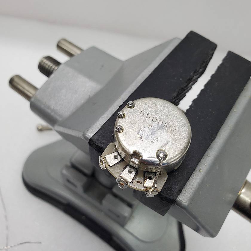
Please avoid using something like the radio pliers shown in the picture below.
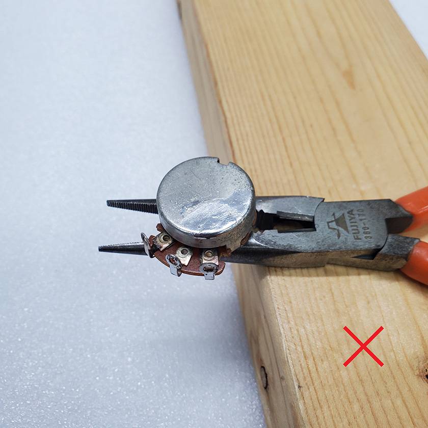
This is insufficient!
Craftsmanship begins and ends with securing.
The final result heavily depends on how well you secure it.
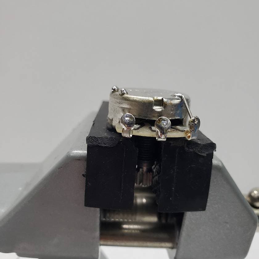
◯ Attaching Terminal 1 to the Back
Bend terminal 1 of the potentiometer with radio pliers and solder it to the back.
Here’s how the terminal numbers are arranged:
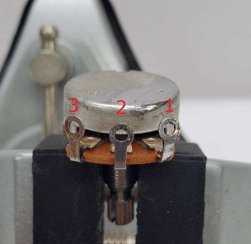
When doing this, make sure the terminal is firmly bent and directly touches the back.
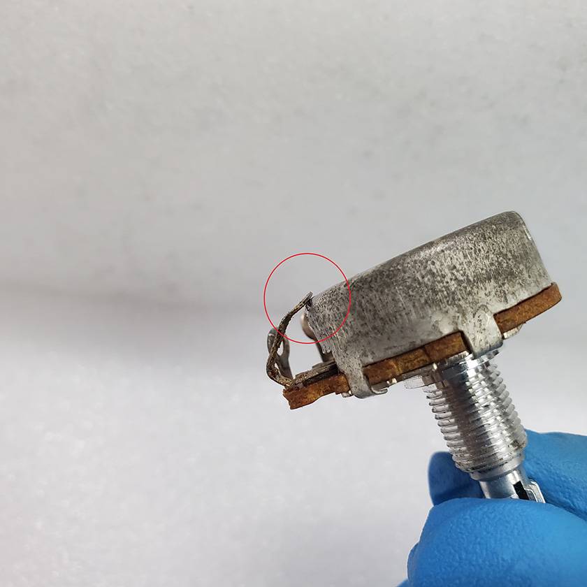
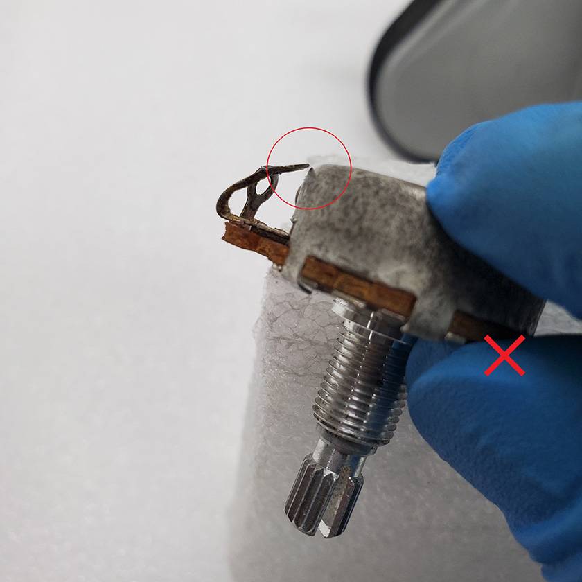
In the picture with ✕, the terminal is slightly raised.
In fact, even if you apply solder in this state, it will conduct electricity.
However, it will be very unstable, leading to intermittent conductivity.
Ensure the terminal is firmly bent to touch the back.
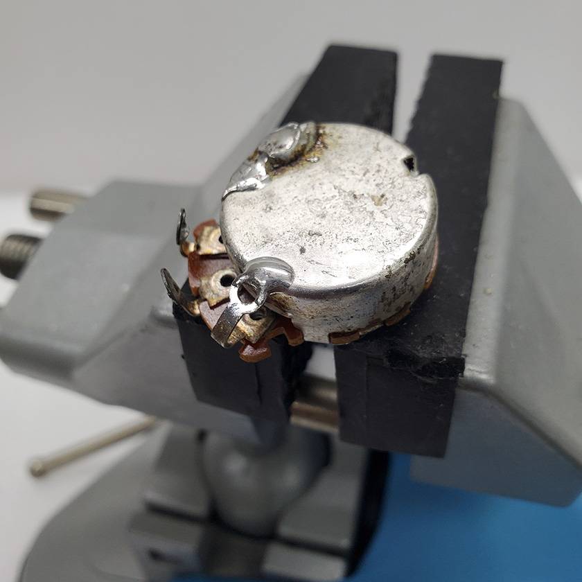
Next, apply solder to fix the terminal and the back.
Note that the back and terminal heat at different rates, so first heat the back sufficiently before heating the terminal and applying solder.
If you heat both simultaneously, the thinner terminal heats faster, causing the solder to flow more to the terminal, potentially preventing a proper connection with the back.
✕
The solder amount should be just enough, not too much or too little.
Personally, I aim to apply the minimum amount necessary for securing the connection, then add just a bit more.
Too little feels unreliable, while adding too much doesn’t serve much purpose.
◯
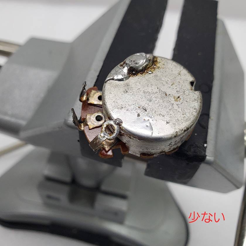
Less solder feels unreliable.
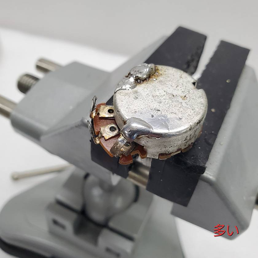
Too much solder doesn’t add much value.
Please keep these points in mind while working.
◯ Attaching Terminal 1 to the Back 2
Depending on the type of potentiometer, bending the terminal might not allow it to reach the back, or bending the terminal could put significant stress on the terminal or its connection point. For those who prefer not to bend the terminal, here’s an alternative method.
First, prepare a conductive material of suitable size, such as tinned wire, resistor leads, diode leads, or capacitor leads.
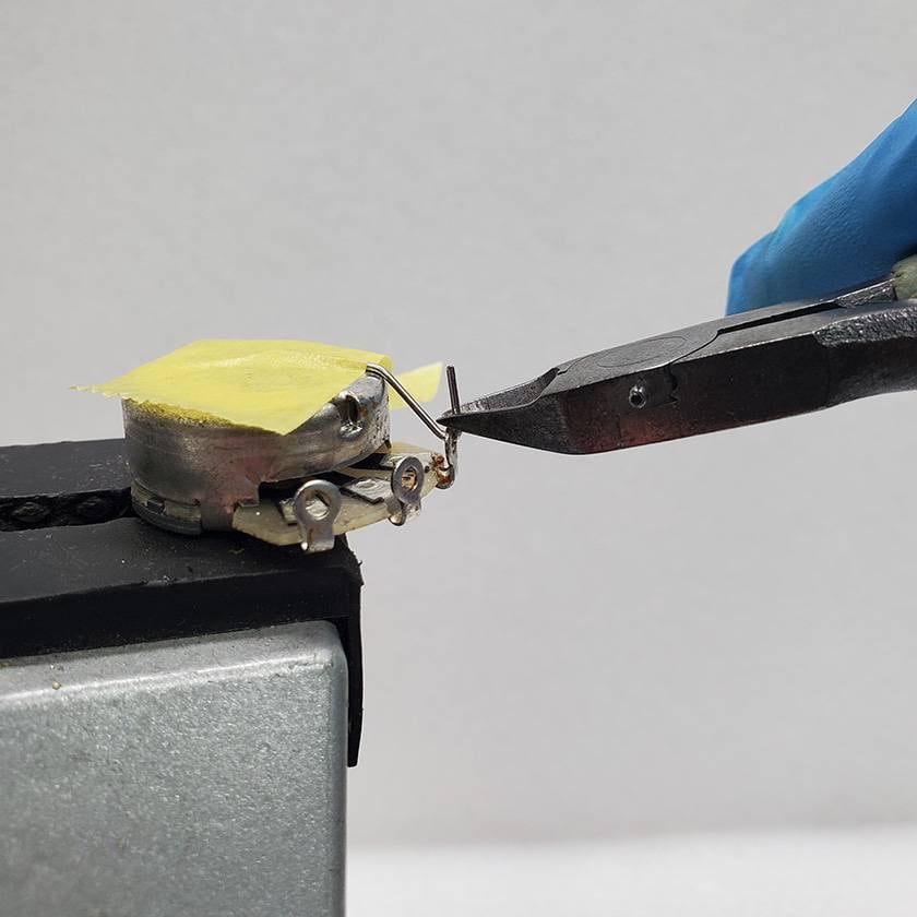
Bend it as shown in the photo, insert it through the terminal hole, and cut it to an appropriate length.
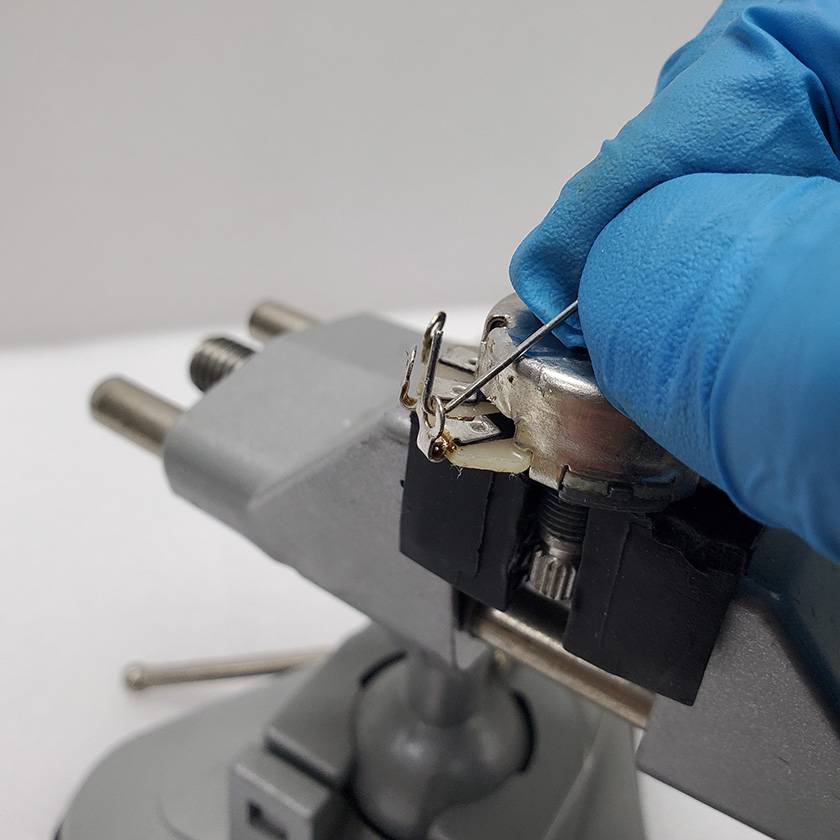
While you could solder the wire to the terminal and cut it afterward, this might put stress on the terminal during cutting. Personally, I prefer cutting the wire beforehand.
Next, use masking tape to secure the wire to the back and apply solder.
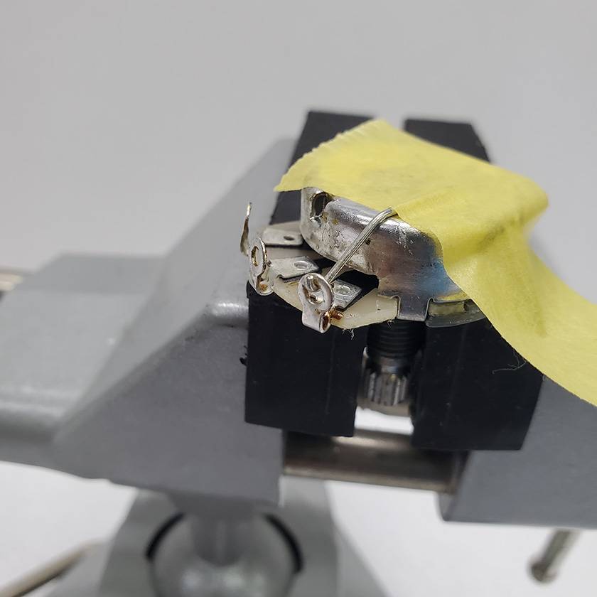
Afterward, ensure the wire is properly in contact with the back and apply solder.
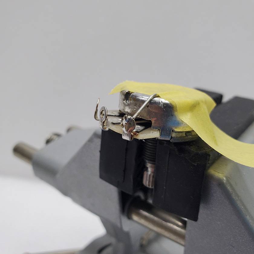
As for threading the wire through the terminal hole, you can wrap it securely, but if you consider reusing the component later, a simple hook method is better.
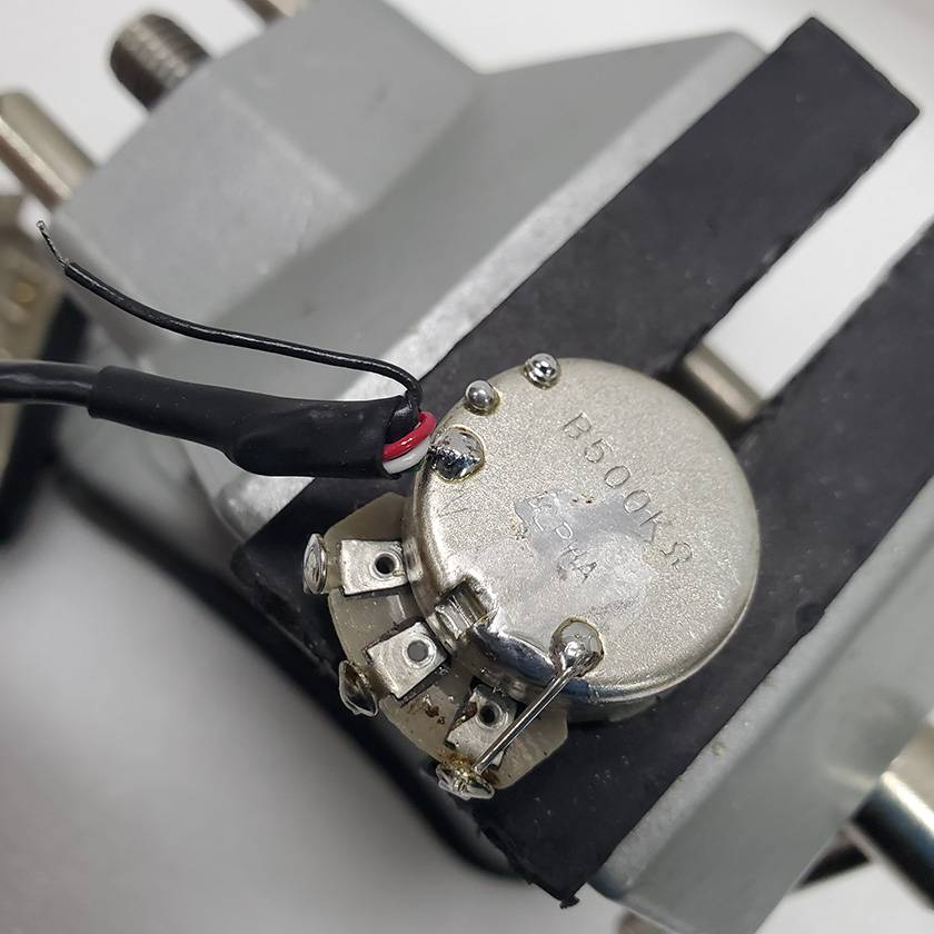
◯ Attaching the Pickup Wire to the Back
After connecting terminal 1 to the back of the potentiometer, the next step is to apply a preliminary layer of solder to attach the wires to the back and terminals 2 and 3.
Start by dabbing small amounts of solder onto the back, as shown in the photo.
At this point, remember that since this is a preliminary solder, you should aim to place the solder lightly on the surface rather than pressing it firmly against the base.
However, it should still be somewhat attached—perhaps just lightly?
Be cautious not to overheat the solder, as it can cause the flux to evaporate, making subsequent wiring more difficult.
Unfortunately, when it comes to the amount of solder, I can only suggest you refer to the photo for guidance. It takes practice and experience to get this right.
As for the terminals, apply enough solder to fill the holes.
*Some manufacturers solder directly to the center of the potentiometer, but since the center contains the rotating shaft, excessive heat can cause damage. I personally recommend soldering to the edge of the back instead.
Finally, it’s time to solder the pickup’s ground wire to the back.
Place the soldering iron on the preliminary solder to heat the base thoroughly, then swiftly insert the wire and remove the iron before the solder flows too much!
This step requires speed, but the key is to proceed calmly and carefully.
Practice is essential—just keep trying.
Personally, I prefer to attach the wire directly to the outside of the terminal.
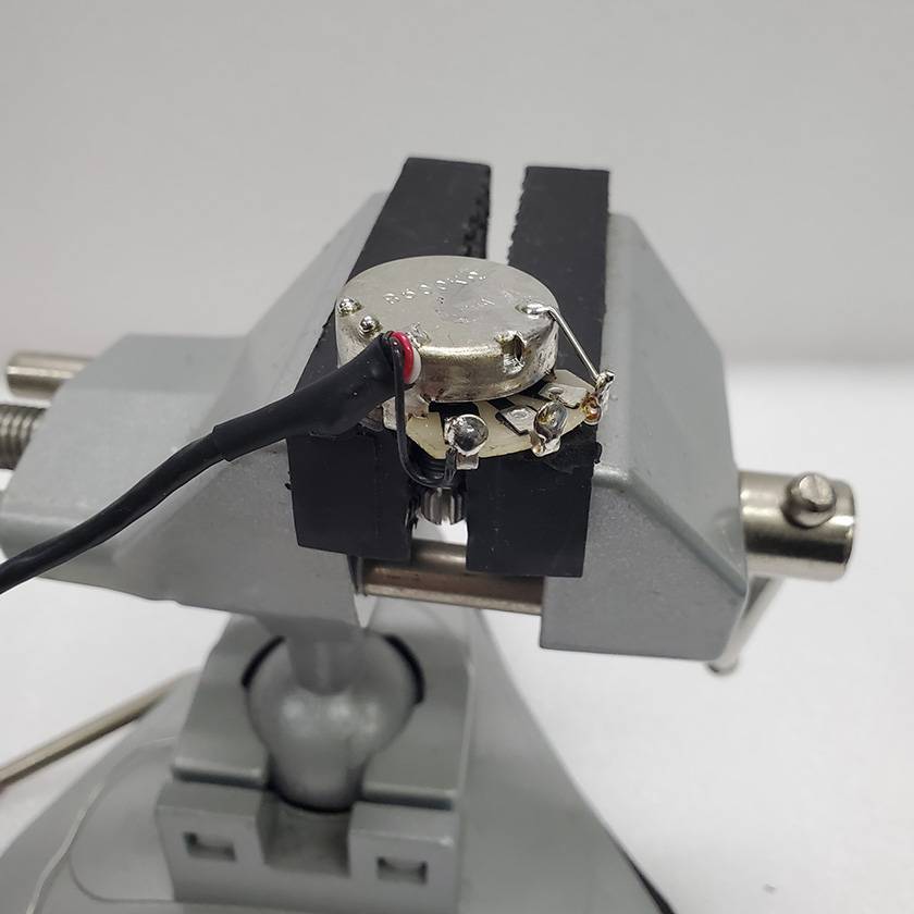
If you choose to insert the wire into the terminal hole and solder it there, ensure that the wire makes good contact with the terminal.
This reduces the chances of future malfunctions or operational issues, providing peace of mind.
How was it? I managed to cover the key points I wanted to explain this time, though I still feel that my lack of vocabulary and writing skills may have left some parts a bit under-explained.
Well, as they say, “Soldering isn’t mastered in a day,” so before replacing your pickup, make sure to practice plenty on any spare potentiometers you have, and give your beloved guitar the best soldering job possible.
See you again on the Sound House Staff Blog.
Thank you for reading.


 ブリッジの種類
 配線カスタマイズ 第1回
 パーツの配線を知ろう
 ピックアップの種類(エレキギター)
 ギターのお手入れ
 お手入れに必要な道具