In the previous article, I wrote about the preparation process for making shielded cables and in this article I will explain the actual implementation process.
If you have not read the previous article, please read this article first.
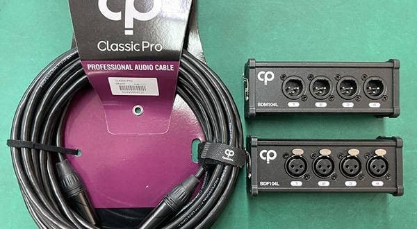
In this article, I am going to use Switchcraft plugs, but if you are new to cable construction, I recommend using relatively inexpensive plugs such as Classic Pro plugs.
Before we begin, here’s a rough explanation of the cable and plug.
For the cable, I’m using the MOGAMI 2524, which I introduced in the previous blog.
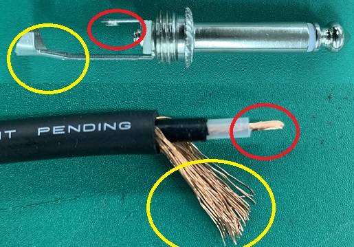
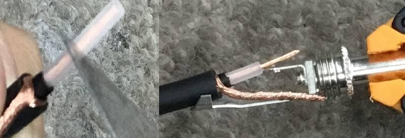
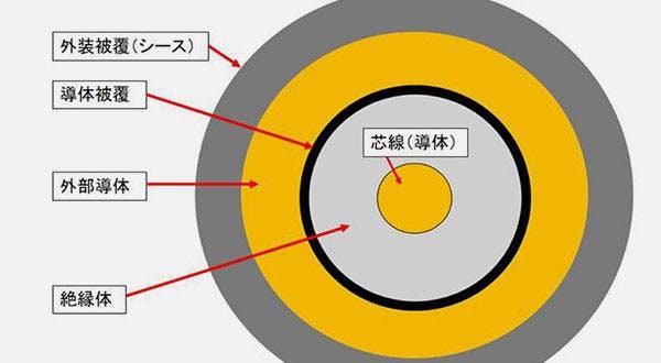
First, let's look at the cable. If you look at the cross section, it looks like the image on the left.
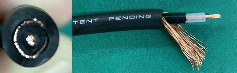
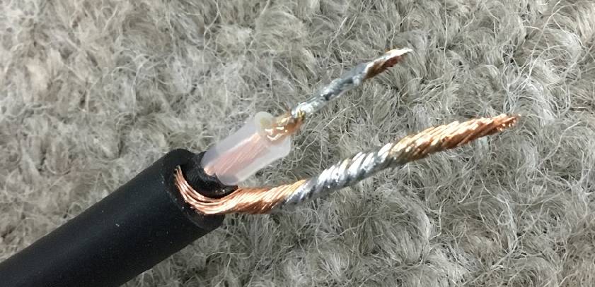
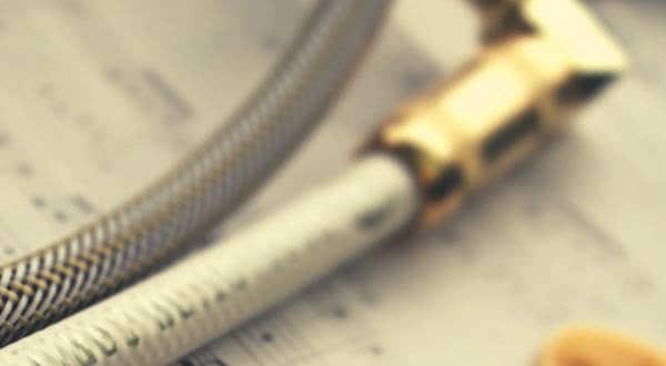
When the conductor portion is exposed, it looks like the one on the right.
A shielded cable consists of a copper wire (core wire), an insulator, a copper wire (shield wire), and a coating, in this order from the middle to the outside. The outer copper wire is called a shield because it prevents extraneous noise from entering the signal. The black vinyl around the insulator inside is conductive vinyl.
Next, here’s a brief explanation of the structure.
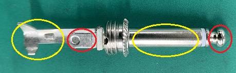
As shown in the image, the color-coded parts are connected to each other. The part in the red circle is called the Tip and the part in the yellow circle is called the Sleeve.
Solder the area in the red circle (core wire and chip) and the area in the yellow circle (shield wire and sleeve) in the image above individually so that they do not touch. And, that’s basically all there is to it.
If either of these parts are not connected, noise or no sound will be produced. Also, if these two places even touch ever so slightly, it will cause a short circuit and result in no sound or muffled sound.
So, let's get down to the actual work.
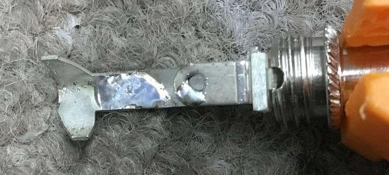
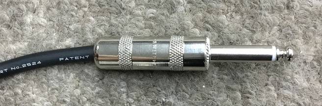
First, let's look at the plug,
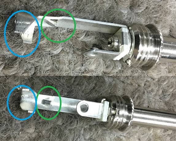
The part circled in blue holds the cable in place, but it’s difficult to work with in the initial state, so I will widen it a little. The green circled part is usually only found on switch craft plugs, so I’m not quite sure what it’s doing here. I think they are there to hook the cable sheath and increase the strength of the cable. When I have tried it in the past, I didn’t think it worked very well, so I’m not going to use it this time and just push it down to flatten it.
Use radio pliers to make it like in the image above.
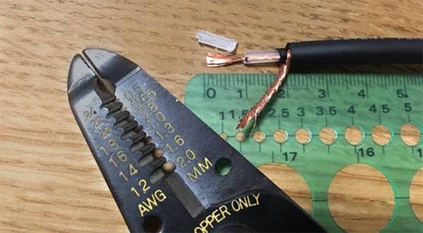
Then measure the length of the cable with a tape measure and cut it. Cut the cable about 6 to 7 cm long (about 3 cm + 3 cm), taking into account the amount you’ll need for soldering. You can use nippers or any other tool to cut the cable at this time.
For your information, this time I made it 4m long. The good thing about making your own shield is that you can make it as long as you like. The standard lengths for ready-made shields are 3m and 5m, but if you think that 3m is too short or 5m is too long, this is a good choice for you. Also, a shield of about 2m may be just right for using at home, so it might be better you make one yourself.
After cutting the cable, first cut the outer sheath.
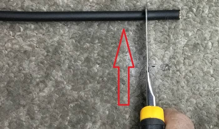
As shown in the image above, place the blade about 1.5~2cm from the tip and cut while rolling the cable straight up while applying light force. If too much force is applied, you might end up also cutting the copper wire. Once the cut has been made to a certain degree, you can cut the cable by pulling it by hand.
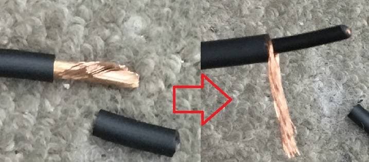
The image on the left shows how the outer copper wire should be cut.
The black vinyl around the insulator of the core wire is conductive vinyl, so cut this off. Even if you have made a shield by yourself, there are unexpectedly many people who do not know that this vinyl is conductive, so be careful.
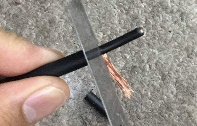
The image on the left is the result of twisting the shield wire.
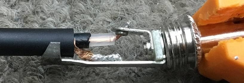
Now, place the shielded wire on the plug.
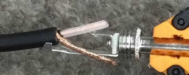
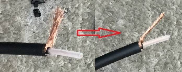
Cut the transparent insulator around the core wire. After cutting it, twist the core wire together.
The length of the wire should be about the same as in the image above.
Finally, let’s start the soldering work.
First, apply preliminary solder to the cable side.
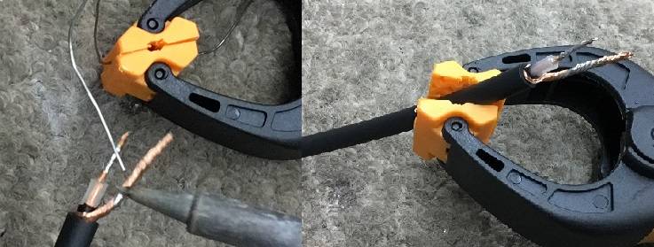
It’s easier to fix the cable and solder with a clothespin or a clip, so I recommend trying this method out first. Also, try to find a shape that is easy for you to work with.
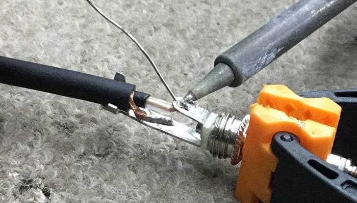
The key takeaway here is to not to melt the solder and put it on the cable. The idea is to heat the copper wire and have the solder flow and soak into it.
Now, lightly place the soldering iron tip on the copper wire to heat it up. Then, apply solder between the tip and the copper wire.
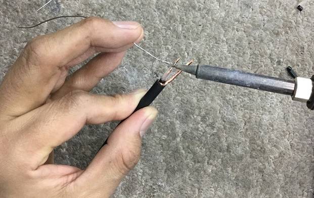
If you do not have anything to hold the cable, hold the cable with the index finger and thumb of your left hand and then hold the solder with your middle and ring fingers. It seems that there are various ways to do this.
Applying too much heat will cause the insulator part to melt, so aim for the edge where it will not melt.
Pre-solder the shielded wire side in the same way.
If it looks like this, then you’re OK. It’s not necessary to soak with too much solder, so do not add too much to make the copper wire too thick as shown in the image.
After reaching this point, the next step is to make the plug.

Next, put the soldering iron tip on the terminal part in the same way, heat it up, and then put solder between the tip and the terminal.
The image is not to put melted solder on the terminal, but to let the solder sink into the terminal.
The surface on which solder is to be applied should be lightly shaved down with sandpaper to make it easier to apply solder.
A little bit of solder on the tip side is enough. On the sleeve side, put a little more solder.
This is about right.。
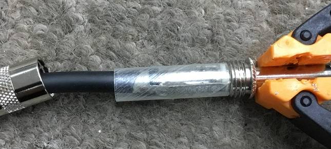
Cover the cable with the cover and the straw for insulation. It is surprisingly easy to forget to do this, so you may cover it further in advance.
Reattach the cable to the plug.
Bend the cable with radio pliers or slightly bend the tip terminal to fit it in.
Cut the excess part.
Adjust the insulation part as well and cut out a little if necessary.
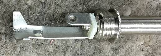
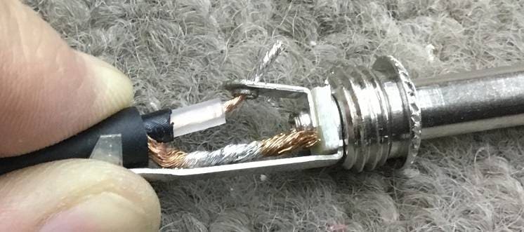
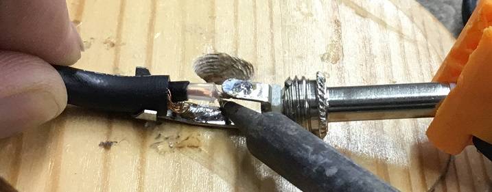
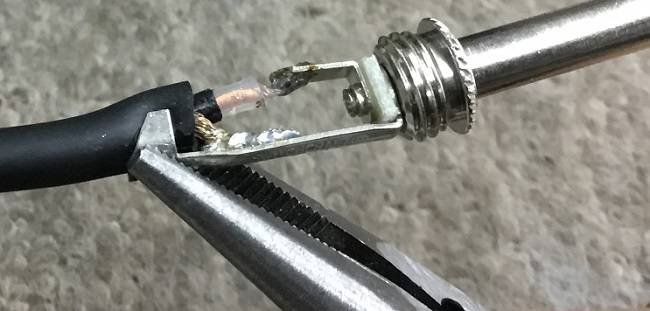
At this point, it is important to ensure that this shape is created, and it is best if all that is left to do is to apply solder and fix it in place.
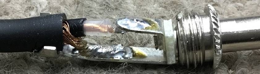
Apply the soldering iron tip and hold it in place while applying solder.
Do the same for the sleeve part.
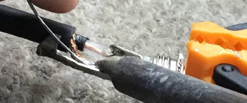
On the sleeve part, the copper wire may not hit the terminal well if you hold the solder, so after pouring out some solder, it’s better to hold the cable while it is hot and apply the solder tip to the cable.
I recommend working on a table because if you do this on a carpet, the bottom of the carpet will burn or melt.
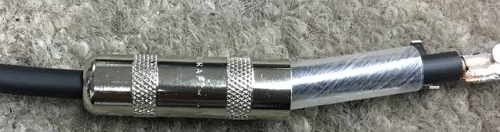
The finished product looks like this.
Bend and secure the cable fixing part with radio pliers. Do not apply too much force so that the cable will not be pulled out, but you need just enough to hold the cable firmly in place.
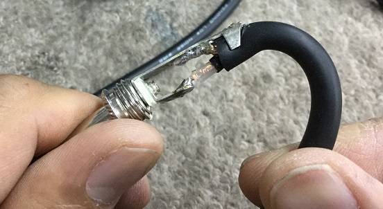
Make sure that the cable does not come off by bending it, or that the tip and sleeve do not come into contact with each other.
Then, put the cover on and now one side is done!
Some people wrap the wires around the terminals on the tip side, others use gauze or cloth for insulation, and still others use various methods for routing the cables around the terminals. I myself usually do things a little differently from the way I have described here.
Experiment with different methods as you get used to them.
Be careful of burns and fire when soldering. The plugs get extremely hot during and immediately after soldering, so please be careful.
Now, we have made a straight type cable.
Be on the lookout for an L-shape version soon!


 ギターケーブルの作り方
 ケーブルの選び方
 虎の巻 ケーブル講座
 ケーブル購入ガイド
 最新コラム&動画をCheck!! OTOYA通信
 サウンドハウス虎の巻 !