Essential Practice Gadget: Page-Turning Pedal
In today’s world, the widespread use of tablets has made it incredibly convenient to carry music scores and audio files anywhere. One of the great advantages that comes with this is the ability to use a page-turning pedal.
For musicians practicing instruments like the saxophone or guitar, where both hands are occupied, a page-turning pedal allows for smooth practice without the need to pause and manually flip through music sheets. While it may take some getting used to, these pedals are a tremendous help. Particularly, Bluetooth-enabled page-turning pedals eliminate the hassle of cables, making them a must-have accessory for hobbyist musicians.
Interestingly, with some basic knowledge of electronics, you can even build your own Bluetooth page-turning pedal using a commercially available microcontroller board (explained in detail [in this article]). In this guide, we’ll introduce how to create a DIY Bluetooth page-turning pedal using a microcontroller board equipped with the "ESP32" chip.
What We’re Building
Music scores displayed on tablets are often in image or PDF formats. Viewer apps for such files typically allow you to move to the next page using the right arrow key (→) or the Page Down (PgDn) key on a keyboard.
To create a page-turning pedal, we’ll configure a microcontroller board to act as a Bluetooth keyboard. When you press the pedal switch, it will send data mimicking the press of one of these keys. This way, the pedal can seamlessly flip pages in your music score viewer.
Materials Needed
ESP32 Microcontroller Board
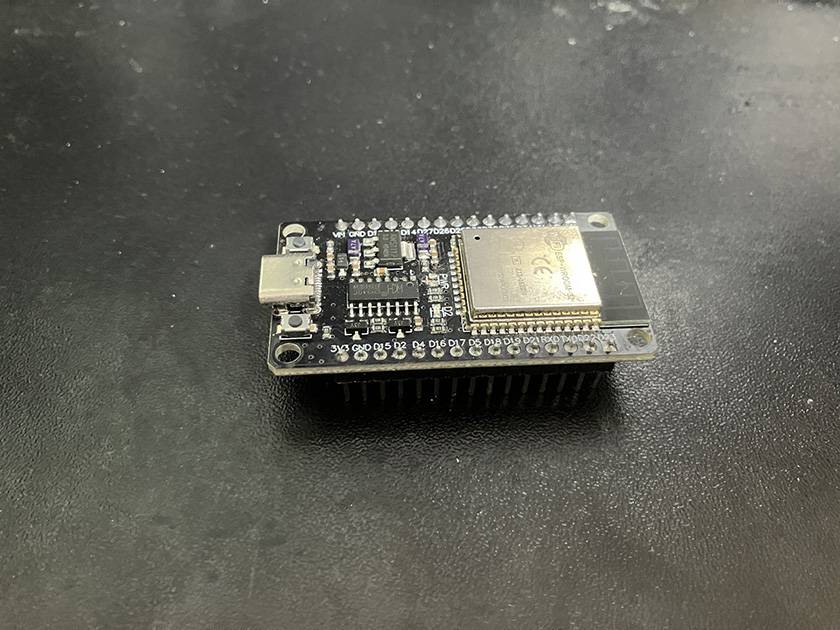
[ESP32 Microcontroller Board]
The ESP32 development board comes with built-in antennas for wireless communication, including Wi-Fi and Bluetooth. It also has a user-friendly Bluetooth keyboard library, making it an excellent choice for this type of project. The board is relatively inexpensive, priced around 1,000–2,000 yen.
Note:
Make sure to use an ESP32 board with a proper certification mark ("技適マーク" in Japan). Using Bluetooth devices without this mark may violate radio wave regulations. Be careful to comply with the law.
USB Cable
Used for programming the microcontroller and powering the device.
Switch and Wires, Enclosure for Mounting
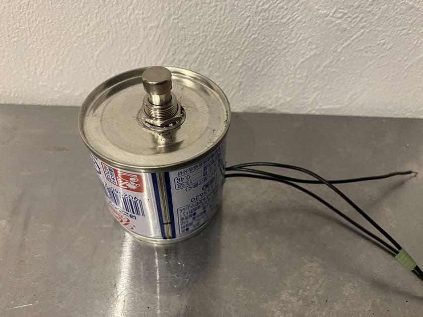
[Foot Switch]
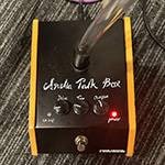
Since the pedal will be operated with your foot, it’s ideal to use a durable switch. In this guide, we’ll repurpose an alternate switch originally designed for guitar effects pedals, along with a canned food tin.
⇒ Creating a DIY MIDI Controller
ArduinoIDE
The tool used to create and upload programs to the microcontroller. It can be downloaded from the official site.
How to Build
Setting Up the Development Environment
Install the Arduino IDE and add libraries for the ESP32 and Bluetooth keyboard functionality. By default, the Arduino IDE does not support writing programs for the ESP32, so additional configuration is required.
This article omits the detailed steps and instead provides links to helpful resources.
■ Additional Notes on Setup
In my environment, even after configuring as described in the links, I encountered the following error during program compilation:
error: cannot convert 'std::string' {aka 'std::__cxx11::basic_string'} to 'String'
If you encounter a similar error during program compilation, it may be resolved by editing specific lines in the Arduino project folder as outlined in the provided link:https://github.com/T-vK/ESP32-BLE-Keyboard/issues/291 Modify the following lines:
Line 106 and Line 117
Error Fix Details
If the error occurs, try editing the following lines in the BleKeyboard.cpp file as described:
From:
- LINE 106: BLEDevice::init(deviceName);
To:
	- LINE 106: BLEDevice::init(deviceName.c_str());
From:
- LINE 117: hid->manufacturer()->setValue(deviceManufacturer);
To:
	- LINE 117: hid->manufacturer()->setValue(deviceManufacturer.c_str());
Creating the Program
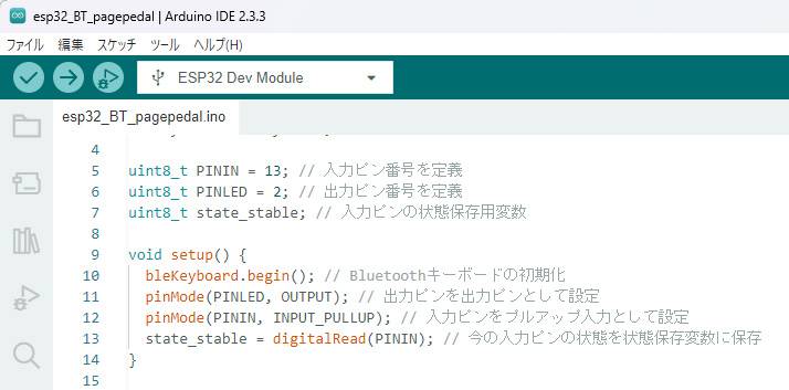
The following program is written to enable the ESP32 board to function as a Bluetooth keyboard. When the state of the input pin changes, it sends the "Right Arrow" keypress data. Additionally, it includes a feature to light up an LED when the Bluetooth connection is successfully established.
Input Pin: Any GPIO pin can be used. Here, GPIO 13 is chosen because it is conveniently located near the power and GND pins on my board.
LED Pin: GPIO 2 is used to drive the built-in LED on the ESP32 board for Bluetooth connection indication.
#include <BleKeyboard.h> // Import the required library

BleKeyboard bleKeyboard; // Create the keyboard object

uint8_t PININ = 13; // Input pin for the pedal switch
uint8_t PINLED = 2; // Output pin for the status LED
uint8_t state_stable; // Variable to store the stable state of the input pin

void setup() {
  bleKeyboard.begin(); // Initialize the Bluetooth keyboard
  pinMode(PINLED, OUTPUT); // Set the LED pin as an output pin
  pinMode(PININ, INPUT_PULLUP); // Set the input pin with pull-up configuration
  state_stable = digitalRead(PININ); // Save the current state of the input pin
}

void loop() {

  if (!bleKeyboard.isConnected()) { // Check if the Bluetooth is connected
    digitalWrite(PINLED, LOW); // Turn off the LED if not connected
    delay(100); // Short delay to reduce CPU usage while waiting for connection
    return;
  }

  digitalWrite(PINLED, HIGH); // Turn on the LED to indicate a Bluetooth connection
  if (pushed() == 0){ // Check for a switch state change
    bleKeyboard.write(KEY_RIGHT_ARROW); // Send the "Right Arrow" key
    // bleKeyboard.write(KEY_PAGE_DOWN); // Uncomment the line below to send "Page Down" instead:
    // bleKeyboard.write(KEY_DOWN_ARROW ); // Uncomment the line below to send "Down Arrow" instead:
  }

}

// Function to detect switch state changes
// Returns 0 if the state has changed, otherwise 1
uint8_t pushed(void){
  uint8_t state_tmp = digitalRead(PININ); // Read the current state of the input pin
  if(state_tmp == state_stable){ // Check if the state is unchanged
    return 1; // Return 1 if no change is detected
  }

  delay(5); // Wait for 5ms to debounce the switch

  if (state_tmp == digitalRead(PININ)){ // Check if the state is stable after the delay
    state_stable = state_tmp; // Update the stable state
    return 0;  // Return 0 to indicate a state change
  }
  else{ // If the pin state changes again within 5ms, it is considered noise.
    return 1;  // Return 1 if the state reverted due to noise
  }
}
■ Additional Notes on Program Creation
The program above demonstrates three key examples (KEY_RIGHT_ARROW, KEY_PAGE_DOWN, and KEY_DOWN_ARROW). However, you can customize it to send other keys as needed.
For other key codes or definitions, refer to the following resources:
- Arduino Documentation
- Bluetooth Keyboard Library on GitHub
Writing the Program to the ESP32
[Writing the Program to the ESP32]
Connect your ESP32 to the computer using a USB cable and upload the program.
Since there are various types of ESP32 boards, it’s important to select the correct model in the Arduino IDE. However, this guide cannot cover all models.If an error occurs while uploading the program, try some flexible troubleshooting steps to resolve issues.
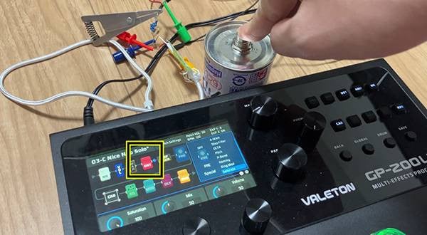
Connecting the Microcontroller and Switch
To wire the switch to the ESP32, follow these steps: Connect the middle terminal of the switch to the input pin on the ESP32 (e.g., GPIO 13). Connect one of the remaining terminals to the GND pin on the ESP32.
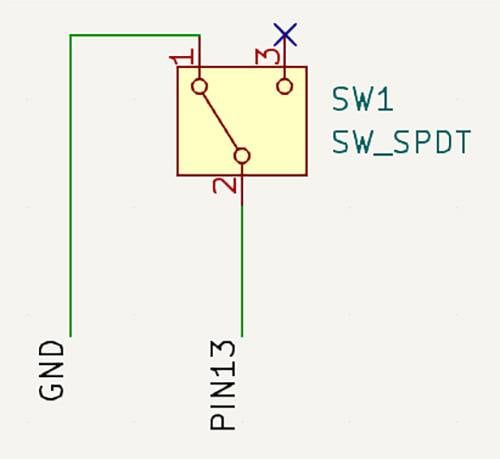
[the wiring diagram]
During the testing phase, soldering is not necessary. Instead, you can use alligator clips and Dupont wires to make temporary connections.
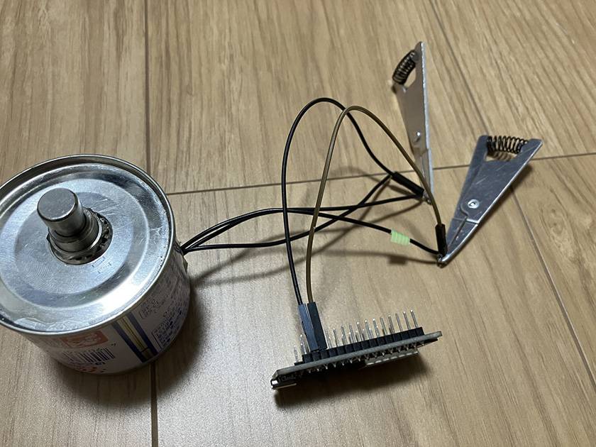
[Wiring setup]
operation check
Once the wiring is complete, connect the microcontroller board to a power source using a USB cable and check for Bluetooth devices on your tablet.
The ESP32 appears as "ESP32 Keyboard" in the Bluetooth settings, showing a successful connection. The diagram shows an example of connecting the microcontroller board to Bluetooth using an iPad.
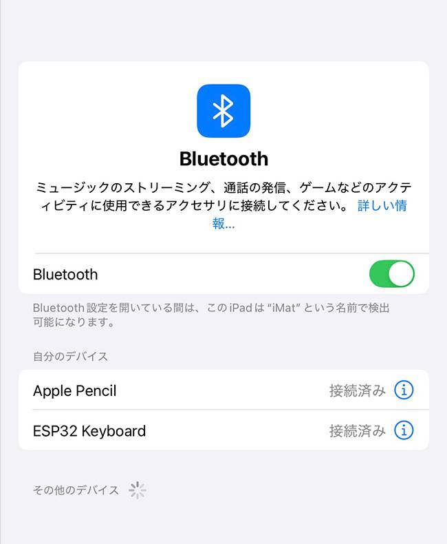
[Bluetooth Connection]
When the connection is established, pressing the switch connected to the microcontroller will cause the tablet to behave as if the "Right Arrow" key on a keyboard was pressed.
For this demonstration, we used the app [Piascore] to load a PDF and tested flipping pages. To make it clear, a dummy PDF with only page numbers on each page was used instead of actual sheet music.
The first part of the demo video below shows the testing process.
Assembly
Once you’ve confirmed that the device works correctly during testing, proceed with the final assembly:
Solder the connections to ensure durability.
Apply insulation (e.g., heat shrink tubing or electrical tape) to prevent short circuits.
Mounting in the Enclosure:
Secure the components inside a casing or enclosure for protection and portability.
Important Points to Note:
Metal absorbs and blocks radio waves, which can interfere with Bluetooth communication.
If you use a metal enclosure, mount the microcontroller board outside the casing.
Position the USB port facing outward to allow easy access for reprogramming in the future.
Applications and Customization Ideas
The page-turning pedal created here is a very simple device that can only move forward one page at a time. However, with some creativity, you can expand its functionality significantly. Here are two examples of possible modifications:
Customized Functionality for Specific Songs
Commercial sheet music often includes symbols like Segno and Coda, requiring musicians to jump backward or forward to specific measures. A simple page-turning pedal may require the player to memorize these locations and navigate manually, which can be mentally taxing.
What if the pedal could be pre-programmed to match the progression of the song? By configuring the microcontroller, each pedal press could automatically flip the necessary number of pages based on the song's sequence.
Example: Custom Page Sequence
Consider sheet music with the following progression:
1 → 2 → 3 → 2 → 4 → 2 → 5 → 3 → 4
Using the pedal, the microcontroller would act based on the number of times the switch is pressed:
- 1st press: Send the "Right Arrow" key once (move to page 2).
- 2nd press: Send the "Right Arrow" key once (move to page 3).
- 3rd press: Send the "Left Arrow" key once (return to page 2).
- 4th press: Send the "Right Arrow" key twice (move to page 4).
- 5th press: Send the "Left Arrow" key twice (return to page 2).
- 6th press: Send the "Right Arrow" key three times (move to page 5).
- 7th press: Send the "Left Arrow" key twice (return to page 3).
- 8th press: Send the "Right Arrow" key once (move to page 4).
- 9th press: Send the "Left Arrow" key three times (return to page 1).
- 10th press and beyond: Repeat from step 1.
This functionality can be implemented easily by creating a variable, such as cnt, to count the number of times the switch is pressed. The behavior can then branch based on the value of cnt.
However, when sending multiple keypress actions in quick succession, if the interval between keypresses is too short, the tablet may misinterpret the inputs. To prevent this, you should use the setDelay function (or a similar delay mechanism) to introduce an appropriate delay between consecutive keypresses.
	// Code snippet
	bleKeyboard.write(KEY_LEFT_ARROW);
	bleKeyboard.setDelay(100); // Delay in milliseconds
	bleKeyboard.write(KEY_LEFT_ARROW);
On my iPad, a 100ms delay worked without issues. However, if misoperations occur, you may need to increase the delay incrementally until you find the optimal value.
Supporting DC 9V Power Supply
Nowadays, most gadgets run on USB power, so securing a USB power adapter for the microcontroller board is rarely an issue.
However, guitarists and bassists often use DC 9V power units with 2.1mm center-negative cables to power their pedals. If you’re already using such a power supply, you might prefer to repurpose it for your microcontroller, rather than adding another USB adapter.
This setup can make your device more compatible with your existing equipment.
VITAL AUDIO / POWER CARRIER VA-08 MKII
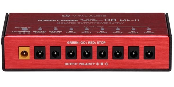
Fortunately, many microcontroller boards can operate safely with a 9V power supply. This guide will explain how to determine if your board supports 9V input and how to modify it for reusing a power unit.
Safety Precautions
If you modify the device to support a 9V power supply, never connect the 9V power source and the USB cable simultaneously. Connecting circuits with different voltages can lead to:
Circuit damage
Fire hazards
To prevent accidents, consider the following measures:
Attach a protective cap to the USB port to avoid accidental connections.
Clearly label the device to indicate the modification.
Double-check power connections before use.
Taking these precautions will help ensure safe operation.
Why the Microcontroller Can Operate on 9V
Before introducing the specific method, let me briefly explain why the microcontroller can work with a 9V power supply.
Voltage Tolerance of Electronic Components
All electronic components have a specific voltage range within which they can operate safely. If a voltage outside this range is applied, the component can be damaged. This range is typically specified in the datasheet under the "Absolute Maximum Ratings" section.
For the ESP32, the allowable power supply voltage range is -0.3V to 3.6V.
Given this limitation, directly applying 9V—or even USB's 5V—would normally damage the ESP32.
The Role of the Voltage Regulator
The reason the ESP32 can safely handle USB's 5V or other higher voltages is due to the presence of a voltage regulator on the microcontroller board.
What is a Voltage Regulator?
A voltage regulator is a component that ensures a stable output voltage, regardless of variations in the input voltage or output current.
How it Works in the ESP32 Board:
The regulator converts the input voltage (e.g., 5V from USB) into the 3.3V required by the ESP32.
This ensures the microcontroller operates safely without requiring a precisely regulated 3.3V external power supply.
Why 9V Works
If the voltage regulator supports a wide input voltage range (e.g., 5V to 12V), it can still provide a stable 3.3V output to the ESP32, even when powered with a 9V source. As long as the input voltage stays within the regulator's supported range, the microcontroller can operate safely.
[DC voltage regulator]
Check the Regulator’s Specifications
There are multiple types of ESP32 microcontroller boards, and they may not all use the same regulator. For safety, it’s better to check the specifications.
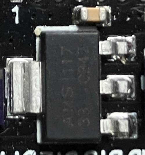
Identifying the Voltage Regulator
Regulators come in various shapes, but a common type is a black rectangular component with:
One thick leg on one side.
Three thin legs on the opposite side.
If you can’t find a component matching this description, you’ll need to methodically look up the part numbers of all the chips on the board.
[DC voltage regulator]
My board has a component similar to the one shown in the link above, labeled "AMS1117."
I searched for this name and found the product specifications.
The specs indicate that the 3.3V output model supports an input voltage range of 4.75V to 10V, with an output voltage of 3.235V to 3.365V. Based on this, it is confirmed that the regulator can handle a 9V input safely.
Connecting a DC Jack to the Microcontroller Board
To power the microcontroller board using a power supply designed for guitar effects pedals, you will need a 2.1mm DC jack.
Where to Find It:
DC jacks can be purchased from electronic component specialty stores or online.
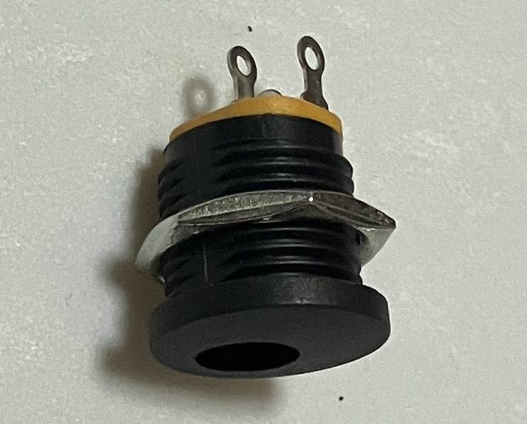
[2.1mm DC jack]
The input pin of the regulator is usually labeled as "5V" or "Vin" on the board. You can identify the correct pin by using a multimeter to check which pin outputs 5V when the board is powered via USB.
Since most guitar effects pedal power supplies use a center-negative configuration, wire the DC jack as follows:
Wiring Instructions:
- DC Jack Center Pin (Negative):
Connect this terminal to the GND pin of the microcontroller board. - DC Jack Outer Pin (Positive):
Connect this terminal to the regulator's input pin on the board (labeled Vin or 5V).
Final Product
By applying the two customization ideas mentioned earlier, a completed version of the device was built using a recycled luncheon meat can as the enclosure.
The operational test of this finalized version can be seen in the latter part of the demo video below.
Conclusion
What started as a "let’s just make it work" approach has turned into a pedal that has become an excellent companion for practice. While a DIY pedal may not match commercial products in terms of performance or reliability, it offers unique advantages:
Tailor it to your exact preferences for a one-of-a-kind device.The choice of enclosure, like a recycled can, can add humor or personality to your project.
If you’re interested in electronics or programming, why not give it a try?
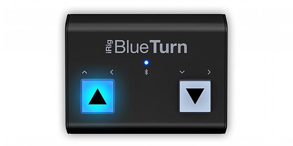
IK MULTIMEDIA / iRig BlueTurn Bluetooth Foot Pedal
The “sound & person” column is made up of contributions from you.
For details about contributing, click here.


![Recommending the App Piascore for iPad Music Scores! [Part 2]](/contents/uploads/thumbs/5/2022/12/20221229_5_20564_1.jpg)
![Recommending the App Piascore for iPad Music Scores! [Part 1]](/contents/uploads/thumbs/5/2022/12/20221229_5_20562_1.jpg)

 譜面を見て、ドラムを叩いてみよう!!!
 K&M タブレットホルダー比較表
 K&M 便利アイテム特集
 まずは弾いてみよう!楽譜の読み方
 タブ譜(TAB譜)の読み方
 iPhone / iPad / iPod用デバイス