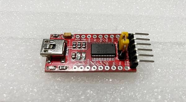
A few days ago, I posted an article on Sound House to the effect that a USB-UART conversion board with two resistors can be used as a MIDI control. However, the USB-UART conversion board requires a computer and it’s difficult to use your feet to switch your MIDI while playing the guitar. So, in this article, I would like to introduce how to make a faux MIDI controller that can be operated with your feet using a microcontroller and footswitches.
What is a microcontroller?
A microcontroller is an integrated circuit that integrates CPU, memory, I/O ports, and various electronic circuits on a single chip and can be reprogrammed to support various types of electronic controls. It’s compact in size and can be bought for a few hundred yen if it is inexpensive, although prices vary widely. A microcontroller board, in which a microcontroller and peripheral components are frequently used when using a microcontroller like a power regulator and test LEDs, are particularly convenient. A single board can be used in various places. This is frequently used for debugging microcontrollers and can be used with most microcontrollers.
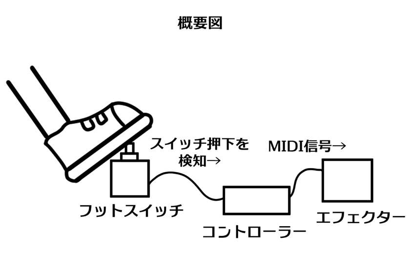
Overview of a faux MIDI controller
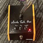
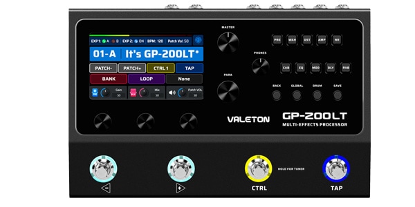
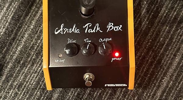
In this article, I will create a MIDI controller with the simple function of sending a predetermined MIDI message when a footswitch is pressed. The MIDI message can be anything, but this time I will send a message to turn on/off the distortion block in the patch of the GP-200LT multi-effects pedal I used in the previous article. I'm not concerned about how it looks, but I do aim to create it within a budget as much as possible, and leave it up to the reader to be creative in how to add further features and make it look better.
Materials for a just-in-time MIDI controller
First, I need to gather the materials to make the controller. The materials I will use are as follows
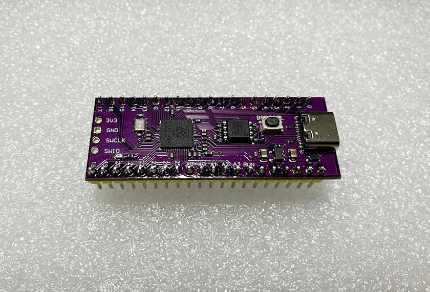
1. Raspberry Pi Pico
There are many types of microcontrollers, but this time I decided to use the Raspberry Pi Pico (a.k.a. “Raspberry Pi Pico”) because it is inexpensive, easy to obtain, and not difficult to use.
Raspi Pico is easy on the wallet because it is available for less than 1,000 yen ( read here ), and there are many mail order sites in Japan that carry it with a wide variety of distributors and dealers. As for the level of difficulty when using it, the method using the software development kit provided by the developer is quite difficult, but using a tool called Arduino IDE, even beginners can easily get it running. In my case, I happened to have one Raspi Pico compatible board at home, so I decided to use it. Since it is a compatible board, the color is different from the regular one, but the usage is the same. It cost less than 600 yen at the time of purchase.
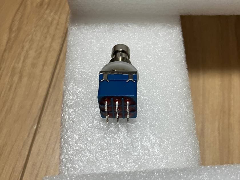
2. 3PDT switch
This is a foot switch to step on with your foot and is used in the creation of homemade effects pedalsfor guitar. In this case, it does not need to be a 3PDT switch since it only switches the input of the microcontroller. SPDT or SPST would have been fine, but I decided to use a 3PDT switch for effects pedals that I had bought several of because I wanted to make my own effects pedals someday. The price is about $200 per switch and they are alternate switches.
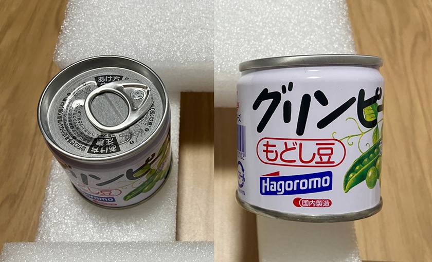
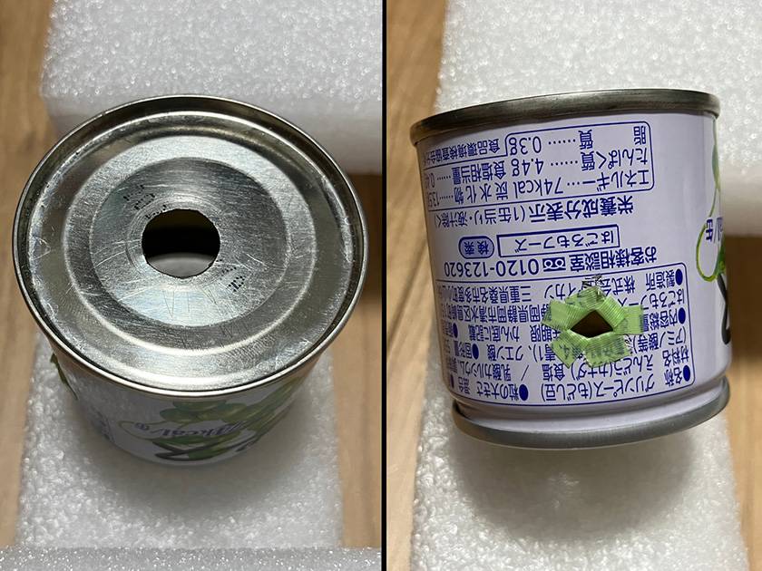
3. Empty green pea cans
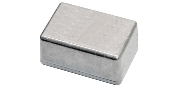
Since my policy this time is “don't worry about how it looks,” I plan to wire the microcontroller with the board bare, but I can’t use the footswitch as it is. It needs a stable and sturdy housing that will not fall apart even if it is stepped on. Sound House sells aluminum boxes suitable for this purpose, but empty cans can also be substituted. I found a small and cute can of green beans at a nearby supermarket that was perfect for a guitar foot switch, so I bought one to try it out. The price is 107 yen.
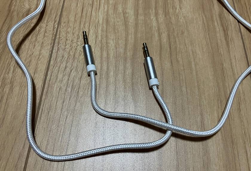
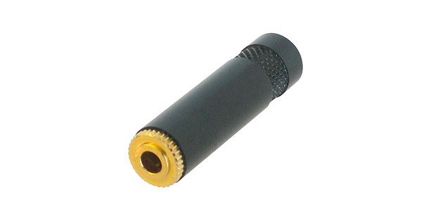
4. Stereo cable
A normal MIDI controller has a 3.5mm TRS jack for outputting MIDI signals. However, since effects pedals also have similar jacks, there is no problem with signal transmission if you plug the controller's output jack into the effects pedal's jack. So, I will use the stereo cable that came with the audio equipment I purchased in the past.
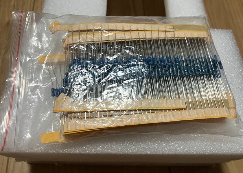
5. Resistor
These resistors are to be connected to TX and VCC of the MIDI output circuit. Raspi pico's signal is 3.3V system, so 10Ω and 33Ω resistors are required (see here). I had a resistor set (purchased for 400 yen) that I had bought before to try my hand at electronic construction, but it had been sitting in a chest of drawers because of its difficulty. Upon further research, I found a 10Ω resistor, but no 33Ω resistor was included. Therefore, I will use three 100Ω resistors instead.
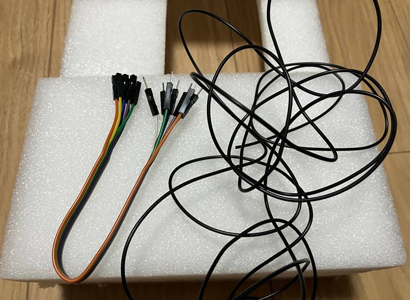
6. Wiring materials
Wiring materials are connected to each component. Raspi Pico has a pin header, so DuPont wire is used. On the other hand, I will use regular cable soldered to the 3PDT switch. These wiring materials were also purchased during my previous attempts at electronics construction.
Circuit diagram of a just-in-time MIDI controller
Next, decide how to connect each component. In this case, I will perform the following wiring.
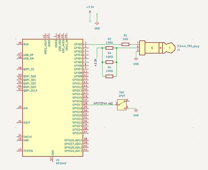
The large rectangle on the left side of the schematic shows the Raspi Pico. The schematic software (KiCad 8.0) uses symbols for individual chips, but you can read them as representing the entire board. The small rectangle in the lower right corner indicates a switch. The switch used in this case is a 3PDT one, but since only one of the three paths is used, the SPDT symbol is the one in the schematic. In the upper right corner is a 3.5mm TRS plug and a resistor symbol.
The TRS plug is connected to the UART pin of the Raspi pico. The UART pin of the Raspi pico can be chosen somewhat freely, but this time I will use the GP0 pin (Reference p.4), which is assigned as the UART0 transmit pin by default. The UART transmit pin is connected to the TRS plug tip via a 10Ω resistor, and the 3.3V supply is connected to the 33Ω (100Ω/3 ) resistor to the ring. The sleeve is connected to grounding.
The footswitch is connected to GP17; any pin other than GP1, the UART receive pin, will do, but I chose this pin because the GP17 is on the end of my board and easy to recognize. Connect one end of the switch to ground and leave the other free. Raspipico can pull up GPIOs internally (connect a terminal of the circuit to power+ with some high resistance), so it doesn’t matter if one end is open.
Programming a Just-in-Time MIDI Controller
The next step is to create a program to write in Raspi Pico. A software development kit (SDK) for the C language is provided by the developer to create a program for Raspi Pico, but designing a program using this is difficult and requires a lot of time and effort to build the environment, so I couldn’t use it. Therefore, I decided to create a program using a tool called Arduino IDE. In this article, I will not go into the details of how to install and configure the tool, but will only show you the actual code I wrote.
#define SWPIN 17  // GP17ピンをスイッチ入力として使用

uint8_t pinstate;  // ピンの状態を保存し、スイッチの切り替えを検出
uint8_t midistate = 0x00;  // ディストーションのオンオフ状態(0x00: オフ, 0x7F: オン)
uint8_t midibuf[3] = {0b10110000, 49, midistate};  // MIDIメッセージのバッファ

void setup() {
  pinMode(SWPIN, INPUT_PULLUP);  // GP17を入力ピンとして設定し、内部プルアップ抵抗を有効化
  pinstate = digitalRead(SWPIN);  // 入力ピン(GP17)の初期状態を保存

  Serial1.begin(31250);  // UARTを31.25kbpsでセットアップ(MIDIの標準ボーレート)
}

void loop() {
  // スイッチの状態が変わったかどうかをチェック
  if(pinstate != digitalRead(SWPIN)){
    delay(10);  // チャタリング対策のため短い遅延を挿入
    if(pinstate != digitalRead(SWPIN)){
      midistate ^= 0x7f;  // ディストーションのオンオフ状態をトグル(反転)
      midibuf[2] = midistate;  // MIDIメッセージの3バイト目(状態)を更新
      Serial1.write(midibuf, sizeof(midibuf));  // 更新されたMIDIメッセージを送信
    }
  }
  pinstate = digitalRead(SWPIN);  // 現在のピン状態を保存
}
The execution of each line is described as a comment in the code; see the previous article for details on MIDI messages. If there are no errors after compilation, write the program to Raspi Pico.
Assembling a Faux MIDI controller
Connect the Raspi pico with other parts after writing the program.
1. Drilling a hole in a can
Make a hole in an empty can for a switch and wiring. The diameter of the hole for the switch is about 1.3cm. The holes for wiring are cushioned with curing tape to prevent the cables from being cut.
2. Soldering the switch and cable
Solder the cable to the switch. The terminals of the switch are arranged in a 3 x 3 configuration, so check with a tester which 3 terminals will function as the switch before wiring. Only the two terminals needed to connect to GP17 and the ground of the Raspi Pico are used, but the other terminals are also wired because they might have a use in the future.
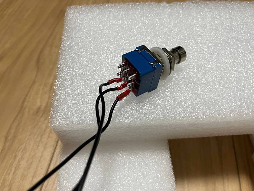
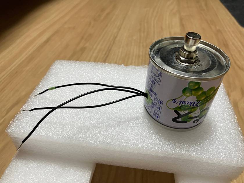
3. Assemble the switch and can
Pull the switch through the hole in the can and secure it with the screws provided. Then, pull the wires through the side holes. Since I only have one color of cable on hand and it is difficult to know which terminal corresponds to which connection, I marked the middle terminal that connects to GP17 with curing tape.
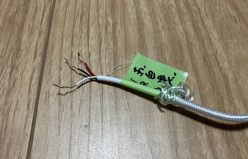
4. Cable modification
The TRS cable that sends MIDI signals is difficult to connect in its original state, so I first cut the cable and peeled off the inner sheath. The copper wire inside is easily frayed, so the tip of the cable should be lightly soldered. Then, taking your tester, check which terminal each cable is connected to on the TRS. In the case of my cable, the red, white, and black cables were connected to the tip, ring, and sleeve, respectively.
5. Temporary wiring and testing
Connect the processed components and Raspi pico with cables according to the schematic, and test them. To make it easier to correct any mistakes, do not solder the cables at this stage, but fix them with something like picks. After completing the wiring, turn on the power to Raspipico, insert the plug of the TRS cable into the effects pedal, and press the switch. In the following video, you can see how the distortion block surrounded by a square is activated or deactivated each time you press the switch.
6. Adjustment and main assembly
Test and adjust the cable length and program contents. If there are no problems, solder, fix any unstable parts, and assemble the whole unit. In my case, I have not yet done the main assembly because I still want to make various modifications. So, I do not have any pictures after the main assembly.
Proposed application of a faux MIDI controller
The MIDI controller I have created this time is a very simple MIDI controller with a single function, but it can be made to be more practical by modifying the program slightly or adding components. Here are some application examples.
- Increase the number of switches:
- Since Raspi Pico has more than 20 GPIO pins, it is easy to add more input switches. By assigning different MIDI messages to each switch, multiple controls are possible.
- Detect double presses, triple presses, long presses, etc.
- Instead of adding more switches, a single switch can detect 2-presses, 3-presses, and long presses, and send a different MIDI message for each. With momentary switches, long presses can also be detected.
- The messages change in turn:
- In your own program, it is possible to send a number of MIDI messages with a single press of a switch. This can be used, for example, to send all the necessary controls for the first song in a live set list at the press of a button, then the settings for the second song, and so on, in that order. Furthermore, it can be more convenient to use the GPIO pins set for output to indicate how many songs are currently being played.
- Additional channel designation functionality:
- DIP switches can be attached to four of the GPIO pins to allow the user to select from 1 to 16 MIDI channels at their inputs. This eliminates the need to rewrite the program every time you change the MIDI channel of your equipment.
- Wireless MIDI with ESP32:
- There is a microcontroller called ESP32 with built-in Wi-Fi and Bluetooth. It costs about 1,000 yen and can be configured in the Arduino IDE; it would be interesting to have two ESP32 boards, one with switches connected to the first board and the other with TRS terminals, so that you can control your equipment wirelessly.
- Pseudo EXP pedal:
- Instead of sending a message only once when a switch is pressed, you can also create a program that continues to send a specific message as long as the switch is toggled. By continually sending MIDI messages that change the parameters of a particular effect at regular intervals, you can control the effect as if you were pressing an EXP pedal.
In Closing
Even though it was rushed, this is a brief introduction to the process of creating a homemade MIDI controller. Even a simple controller can be used in a variety of ways, depending on your creativity. I hope this column has been useful for your musical activities and helps you to expand your music enjoyment.


![[2023] Top Recommended Popular MIDI Keyboards](/contents/uploads/thumbs/2/2022/6/20220608_2_18195_1.jpg)

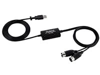
 BOSS MIDIケーブルで広がるパフォーマンスの世界
 IK Multimedia iRig特集
 USB接続MIDIインターフェイス
 USB接続対応のMIDIキーボード
 エフェクターのつなぎ方
 エフェクターの種類