This article describes the reading mechanism of CDs, which were first commercialized in 1982, exactly 40 years ago this year, 2022. Although optical disc technology can now be considered a classic, it is based on delicate and advanced control technology.
■ Overview of Reading Mechanisms
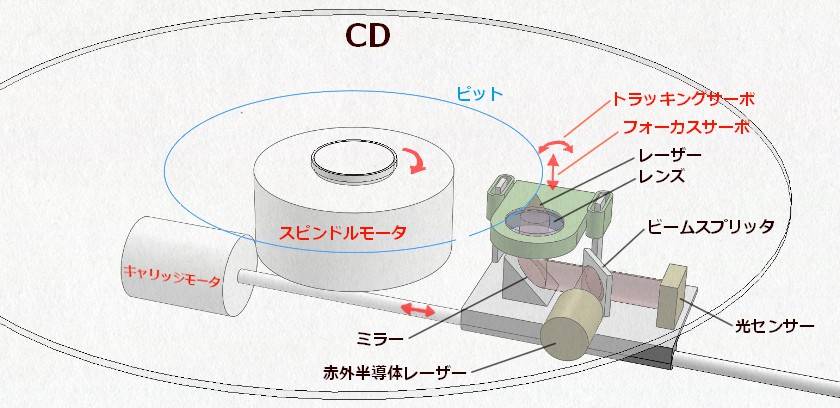
The four drive systems required to read the tracks on a disc are shown in red. The roles of each are as follows.
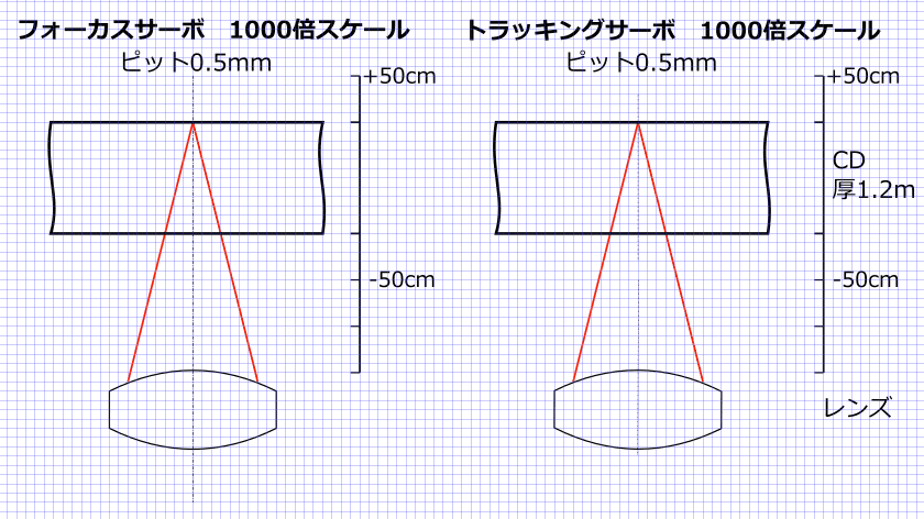
■ Focus servo Circuit Focus adjustment
A disc is not perfectly flat and is warped to some degree. Therefore, the tracks on the surface always oscillate up and down. Although there’s a difference of about 0.5 mm that may appear depending on the condition of the disc, the reading device can read a difference of about 1 mm without any problem. In other words, when the disc rotates at high speed, the vibration is about 9 revolutions per second. If there‘s a 1mm difference in height, it is necessary to move the focus to the maximum extent 9 times per second, but while adjusting the focus, the system continues to accurately read the groove.
■ Tracking servo Error correction
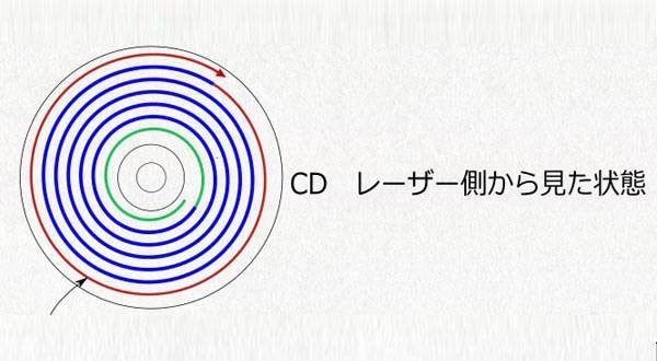
The pit tracks are spiral-shaped, but the width of the pit is 0.5µm, and the distance from the next pit is 1.6µm. Tracking servo is necessary to accurately trace a track without losing sight of it. Since the center of the disc and the center of the motor are only fixed by a simple needle, there’s always electronic eccentricity. In other words, the disc cannot rotate in a perfectly concentric circle with respect to the motor shaft. Misalignment continues to occur in the direction of the arrow in the figure. This is how we compensate for this.
■ Spindle motor adjustment of disk rotation speed
Reads at a constant speed relative to the pit. In other words, the speed of disc rotation changes between the inner and outer circumference. The adjustment method determines the optimum rotation speed from the read data, corrects it, and keeps the speed constant.
■ Carriage motor Feed control
This control is used to move the entire pickup. It is controlled by turning worm gears. The direction of this movement is similar to that of the tracking servo, but the tracking servo performs detailed movements, while the carriage motor does not. During playback, the carriage motor moves slowly from the inner to the outer circumference. When playback is finished, it returns to the innermost circumference at once.
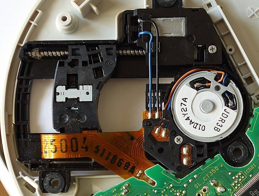
The photo below shows the actual pickup section of a CD player.
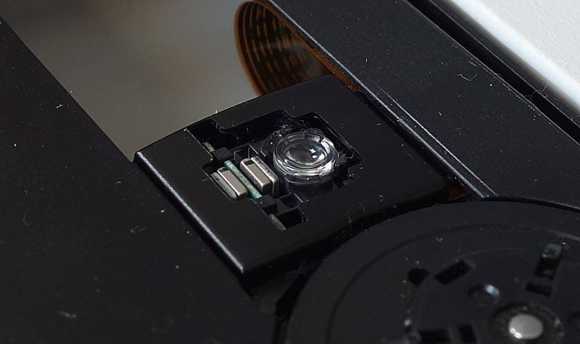
The spindle motor and carriage motor can be seen from the back.
■ Image at 1000x scale
The above drive control is used to optically read the tracks of a CD, but the size of the tracks is so small that it is difficult to imagine that they’re actually there. The figure below shows the CD groove at 1000 times the size. 1000 times is a convenient number because it only requires a change in the unit.
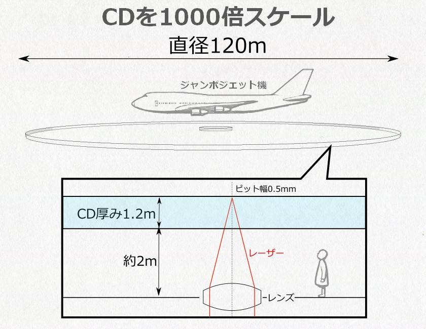
A CD is a disk that’s 120 meters in diameter and 1.2 meters thick. The pit is 0.5 mm wide and 0.1 mm high, and the laser is aimed at it from a lens about 3 m below. The CD rotates at high speed. The actual speed is 1.25 m/sec, but on a 1,000-fold scale, the speed is 4,500 km/h. A bullet train spins at 300 km/h, a bullet train at 4,500 km/h, while a regular train moves at 4,500 km/h. A bullet train goes 300 km/h, a jumbo jet 500 km/h, and anything over 1000 km/h is a fighter jet or rocket. The laser is not allowed to hit the track of a neighboring truck 1.6mm away.
Furthermore, the track is not always 3 meters away, but it oscillates up and down about 1 meter at about 9 times per second. The pit is also eccentric, so it oscillates from side to side as well. Even under such conditions, we are not allowed to make any mistakes, and we must keep the laser on the track for 74 minutes without error. Obviously, it’s impossible for a human to do this manually. A CD player can perform this kind of work without a hitch.
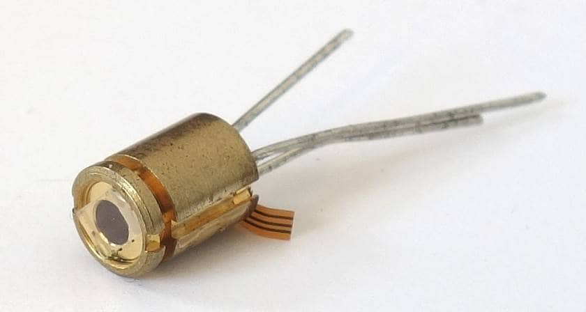
■ Laser (780nm)
CD players read signals by shining a light on a track as wide as 0.5μm. The light is focused to a very small point of about 2 µm, which is impossible to achieve with LEDs because they cannot be made smaller than the light-emitting surface. Lasers, on the other hand, can produce well-defined coherent waves. Laser technology was essential for CD development. Around 1980, however, only Sharp was able to mass-produce infrared semiconductor lasers. Sony began in-house production of semiconductor lasers in 1985 and they were also active in the development of elemental technologies. The laser is one of the great inventions of the 20th century.
The laser below was extracted from a broken Discman, so I think it was made by Sony. I remember when I was a kid, I found out that lasers were used in CD players and I wanted a laser more than anything else in the world.
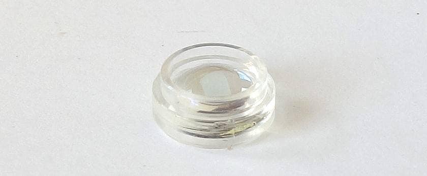
■ Plastic Lenses
The lens used to focus the laser is very important. However, lenses are originally made by cutting optical glass, and to achieve the performance required for CDs, multiple spherical lenses had to be stacked on top of each other, making them heavy and expensive. There is now an aspherical lens that uses only one piece of glass. However, aspherical lenses made of glass are also expensive. This is where plastic lenses came in. Plastic lenses could be mass-produced easily and inexpensively once the molds were made. Konica was the dominant company in this field. Other companies had a hard time trying to enter the lens development market, and Konica's proprietary know-how allowed them to dominate the market for many years.
The photo below shows an aspherical plastic lens with a coating on the surface that is believed to have been made by Konica.
■ Signal Conversion Circuit
In addition to the above mechanisms, CD players also contain DA converters and other components that convert read digital audio into analog audio. Since audio files are now often played back from a PC, the DA/AD conversion part of a DAC or audio interface is attracting attention. Here, audio digital signals are converted to analog signals and vice versa. This is an essential function and has been around for a long time, but it is an extremely important part. In audio equipment, the more the input/output equipment, the greater the difference in sound quality, and in the digital age, the difference in digital/analog conversion is too large to be ignored. In this ever-evolving field, semiconductor manufacturers are responsible for the ICs at the heart of audio equipment. I will explain DA/AD conversion in the near future, as there are some complicated issues such as jitter.
The “sound & person” column is made up of contributions from you.
For details about contributing, click here.


 PC向けDJソフトの選び方
 TASCAM CDプレーヤー/レコーダー比較表
 Pioneer DJ/AlphaTheta比較表
 YAMAHA CD-S303RK
 DJを始めるのに必要なもの?
 DJ入門講座