Here is an explanation of the disk structure of the CD. The standard music CD was developed in 1981 as the CD-DA (Compact Disc Digital Audio) by Sony and Philips. While there are extended formats, I will focus here on the most basic aspects.

■ Main Specifications
Sampling frequency: 44,100 Hz (Nyquist frequency: 22,050 Hz)
Quantization bit depth: 16 bits (96 dB)
Stereo: 2 channels
Capacity: 74–80 minutes (650–700 MB) of audio
Can store up to 99 tracks
Each track can have up to 100 indexes. Index 1 is the start of the track, and index 0 is the pre-gap position. However, it seems that this feature is rarely used today, as most CD players do not have an index search button.
■ Disk Structure
The physical structure of the disk is as follows:
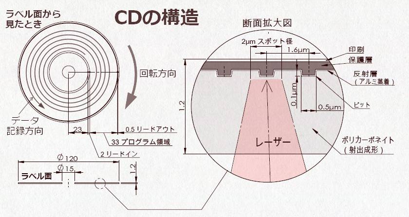
The primary material is polycarbonate, and the pits, which represent the audio signal, are transferred from the master disc through injection molding. The pits are extremely small, with track spacing of 1.6 μm, which is not visible to the naked eye. There is a reflective layer made from aluminum deposition to reflect the laser. The 10 μm protective layer over the reflective layer is crucial. If this protective layer peels off, the reflective layer is damaged, and the CD becomes unreadable. Additionally, the aluminum layer is only 0.1 nm (nanometer) thick, so it can turn transparent and become ineffective if it oxidizes. Therefore, humidity control is also important for maintenance.
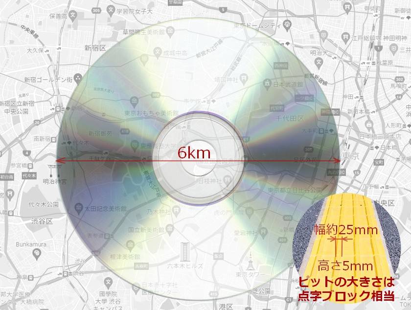
To help visualize the size of the pits, I’ve drawn a map with the assumption that the CD’s diameter is 6 km. The distance between Tokyo Station and Shinjuku Station is approximately 6 km. At this scale, the pit width would be 25 mm and the height 5 mm. This size is similar to the tactile paving blocks you often see on the streets or at train stations.
The audio signal is recorded in a spiral pattern from the inner to the outer ring of the disk. The rotation direction of the disk is clockwise when viewed from the label side. The pit reading speed is set to CLV (Constant Linear Velocity) at 1.2–1.4 m/sec, which means the rotational speed changes when reading inner and outer data. The rotational speed varies between 198 to 535 rpm. At its fastest, the disk rotates about 9 times per second.
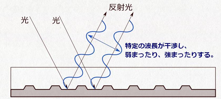
The reason why the CD appears to sparkle with a rainbow is due to the pit spacing being close to the wavelength of light (0.38–0.77 μm), which causes diffraction and interference.

When viewed in a diagram, it looks as follows. Due to the narrow spacing between the pits, light interference occurs depending on the angle at which light enters. As a result, specific wavelengths are either weakened or strengthened, causing the colors to separate, which gives the appearance of a rainbow.
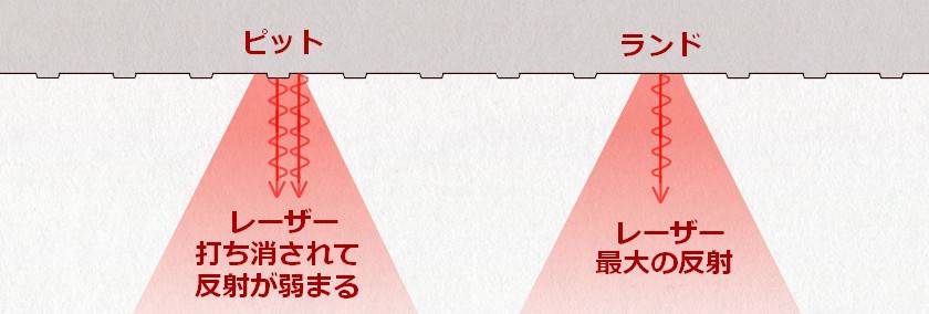
When the pits are enlarged from the laser's perspective, they look as follows. A "pit" in Japanese refers to a hole or a depression, but in this case, it represents a protrusion that’s about 0.1 μm high, appearing as if viewed from transparent ground.
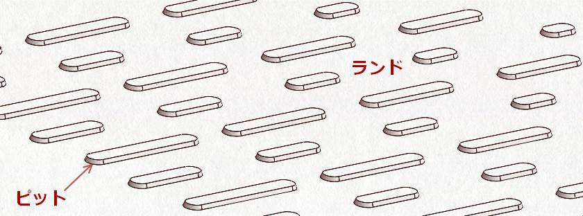
The length of the pits is determined by 9 different types, from T3 to T11. When the linear speed is 1.25 m/s, they are represented as shown in the diagram below. Dimension-wise, the longer the pit, the slightly longer it is. Areas other than the pits are called "lands," which reflect the laser to the maximum extent. The spacing between pits, like the pits themselves, is also divided into 9 types. Additionally, the transition between pits and lands is represented as 1, while all other values are 0.
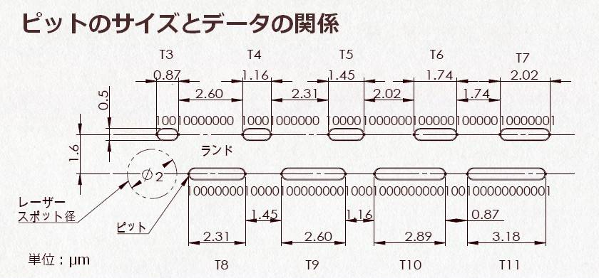
| T | Length | Data |
| T3 | 0.87 μm | 100 |
| T4 | 1.16 μm | 1000 |
| T5 | 1.45 μm | 10000 |
| T6 | 1.74 μm | 100000 |
| T7 | 2.02 μm | 1000000 |
| T8 | 2.31 μm | 10000000 |
| T9 | 2.60 μm | 100000000 |
| T10 | 2.89 μm | 1000000000 |
| T11 | 3.18 μm | 10000000000 |
The reason the lengths are limited is that it's not allowed to deviate from the current track being read. In order for the track to continuously be recognized, the number of consecutive zeros is restricted to between 2 and 10. If a long sequence of zeros occurred in the land area, there would be no pit, making it impossible to determine where to read from. In other words, the pits appear at a certain frequency, allowing the laser's position to be continuously corrected to ensure that it stays on the track. The laser traces the spiral all the way to the end. Additionally, the rotation speed is adjusted by continuously correcting to ensure that the pits are accurately read.
In the physical reading, when a 780 nm infrared laser light enters the polycarbonate, the wavelength changes to 494 nm due to the refractive index. The height of the pits is 110 nm, which is about 1/4 of the wavelength. The laser not only hits the pits but it’s also adjacent to the lands. The reflected wavelength becomes 180° out of phase, and the reflections from the pits and lands cancel each other out. As a result, the reflectivity decreases, and the sensor detects a darker signal. This is how pits and lands are distinguished. The reason why the laser's wavelength and the height of the pits are defined is explained by this mechanism.
As it can be seen from the specified lengths of the pits above, it’s clear that PCM data is not directly recorded as it is. The process of how audio signals are processed and recorded onto a CD involves a somewhat complex procedure, which I will explain in the next article.
The “sound & person” column is made up of contributions from you.
For details about contributing, click here.


 PC向けDJソフトの選び方
 TASCAM CDプレーヤー/レコーダー比較表
 Pioneer DJ/AlphaTheta比較表
 YAMAHA CD-S303RK
 DJを始めるのに必要なもの?
 DJ入門講座