‘True bypass’ refers to a type of pedal switching where the guitar signal is output as-is when the effect is off, contrasting with ‘buffered bypass’. A true bypass pedal internally features two signal paths: one for the effect and one for the dry signal, switched between by a switch.
While the concept of switching between two paths might seem straightforward, there are subtle considerations to ensure safety and reliability. This time, let’s delve into those details.
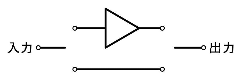
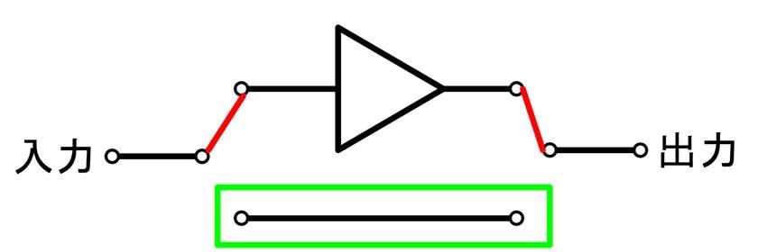
The simplified internal structure of a true bypass pedal is shown below. The triangular symbol represents the effect circuit, and the two horizontal lines represent the two signal paths. How should the switch be arranged to alternate between these paths?
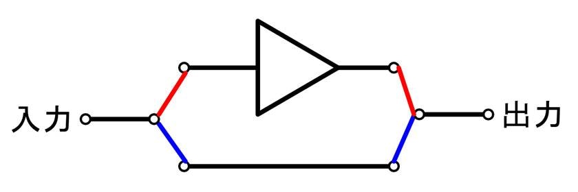
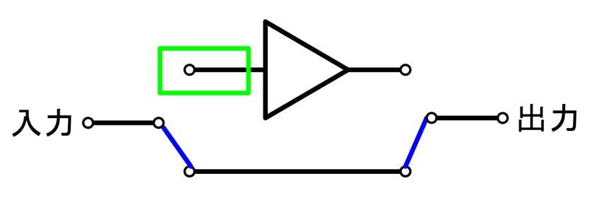
A common approach might look like the diagram below. The red line represents the switch state when the effect is on, and the blue line shows the true bypass state. While this setup controls the effect application perfectly, it’s recommended to avoid this configuration as it poses a risk of circuit damage.
Let’s shift topics slightly. You’re probably familiar with the idea that “static electricity is extremely high voltage and can cause electronic device failures.” In fact, certain parts of electronic circuits are prone to static buildup, particularly at ‘high-impedance terminals’.
Static electricity occurs when electric charge accumulates. Imagine a scenario where charge builds up on a terminal in an electronic circuit. If the terminal’s impedance is low, current flows easily, preventing significant charge accumulation and thus avoiding static buildup. However, in high-impedance terminals, charge accumulates without much current flow, potentially raising the voltage beyond the component’s tolerance and causing damage. This is why electronic circuits are generally designed to minimize high-impedance states or include static protection circuits when high impedance is necessary. Guitar pedals and amplifier input terminals are designed with very high impedance, and quality products include static protection.
Even with protective measures, it’s best to avoid static buildup by not creating high-impedance states. Let’s examine the diagram above to identify areas prone to high-impedance conditions.
Let’s first consider the state when the effect pedal is on. In this case, the lower path is not connected to anything, resulting in an infinitely high impedance, allowing for indefinite charge accumulation.
Now, what happens when the pedal is off and in true bypass mode? In this scenario, the input of the effect circuit becomes a high-impedance point. As the saying goes, ‘high in, low out’ — signal transmission circuits are typically designed with high impedance at the input and low impedance at the output, so there’s no issue on the output side.
As we can see, the circuit in the diagram exhibits high-impedance points both when the pedal is on and off. How can we design the circuit to avoid these high-impedance conditions? There are various approaches, but one effective solution is to arrange the switch as shown below, ensuring that no high-impedance terminals appear in either state.
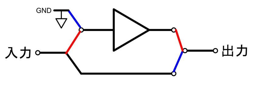
In the diagram above, the switch on the left is now placed at the input of the effect circuit rather than the overall input. The switch toggles the connection between the effect input and either the effect circuit or ground. As in the previous diagram, the red line represents the switch state when the effect is on, and the blue line represents the state when it is off. Let’s consider the impedance of each part of the circuit when the effect is switched on and off.
First, when the effect is on and the switch is in the red state, previously, the true bypass path was not connected to anything, creating a high-impedance condition. However, in this setup, the overall input is connected to the effect circuit’s input. Since the overall input is typically connected to the low-impedance output of the preceding circuit stage, the impedance remains low. The output side already has a low impedance, so there are no issues there.
Next, let’s consider the situation when the effect is off, and the switch is in the blue state. In the previous case, the input of the effect circuit was not connected to anything, resulting in a high-impedance state. However, in this setup, that part is now connected to ground, allowing any accumulated charge to flow directly to ground.
I hope this illustrates that even a seemingly simple task like switching between two signal paths requires careful consideration of several factors.
The column “sound & person” is made possible by your contributions.
For more information about submissions, click here.


![“The Road to Your Complete DIY Equipment” 2nd Edition: The Illusive Vintage Sound! Amplified Buffer Get your hands on the legendary device exclusively used by professionals [Circuit Edition Part 2]](/contents/uploads/thumbs/2/2023/5/20230515_2_22601_1.jpg)

 BOSS Xシリーズ
 UPDATETC ELECTRONIC ブランドページ
 【初心者向け】エフェクター講座
 ベース用エフェクターの種類
 エフェクターのつなぎ方
 エフェクターの種類