


![]()
- Pianos / Synthesizers
- SYNTHESIZER
- Modular synths / sound modules
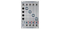
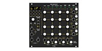
- Tiptop Audio/Buchla 296t Spectral Processor
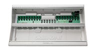
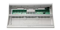
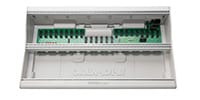
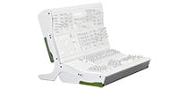
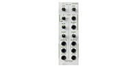
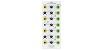
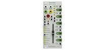
Tiptop Audio / Buchla 296t Spectral Processor


Variations
Back Order
BD808 Bass
Back Order
CB808 Cowbell
Back Order
HATS808 Hi-Hats
Back Order
MA808 Maracas
RS808 Rimshot
Back Order
SD808 Snare
Back Order
BD909 Bass
Back Order
CP909 Clap
Back Order
CYMBL909 Cymbals
Back Order
HATS909 HI-Hats
Back Order
RS909 Rimshot
Back Order
SD909 Snare
Back Order
909-TOMS
Back Order
Sequential Voltage
Back Order
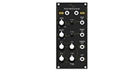
Dual Voltage Processor
Back Order
Dual Oscillator
Back Order
Source of Uncertainty
Back Order
Quad Function
Back Order
Quad Lopass Gate
Back Order
Spectral Processor

Back Order
Blind Panel 2 Set
Back Order
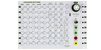
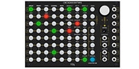
Circadian Rhythms
Back Order
Forbidden Planet
Back Order
MISO
Back Order
Mix7
Back Order
Mixz
ONE
ONE x 4 4台セット
QuantiZer
Back Order
VCA
Back Order
Wayout8
Back Order
Z-2040 Prophet 5 VCF
Back Order
Z-4000 NS VC-EG
Back Order
Z-8000 Matrix Sequencer

Back Order
Zeus Access

Back Order
Zeus Access Dual
Back Order
Zverb White
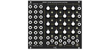
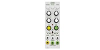
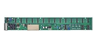
This is a modified version of the Buchla Synthesizer User Guide by Daniel J. Schedit (November 16, 1982) for use with the 296t.
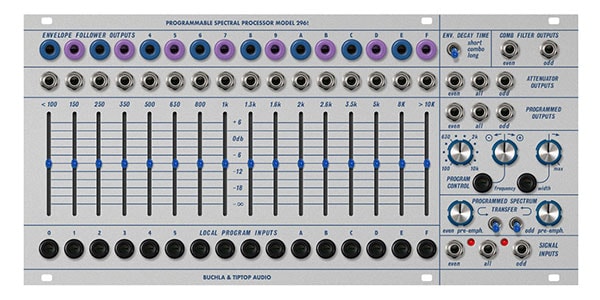
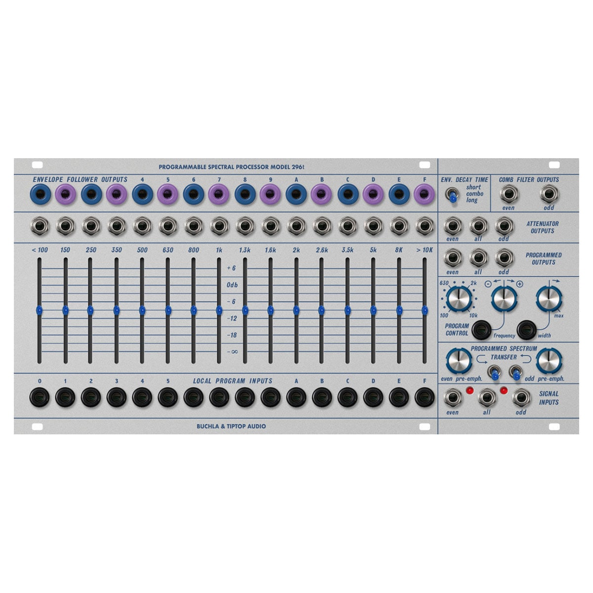
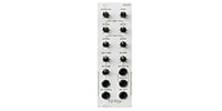
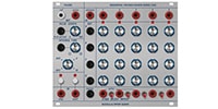
■ATTENUATOR OUTPUTS
The Signal Inputs jacks in the lower right are for “even” (eight even-numbered bands), “all” (all 16 bands), and “odd” (eight odd-numbered bands) signal inputs. Note that these represent even or odd numbered bands, and not even or odd harmonic bands. The ATTEEUNATOR OUTPUTS on the right of the module also have signal outputs for “odd”, “even” and “all”.
When a signal is patched to the “all” signal input and taken out of the “all” ATTEEUNATOR OUTPUTS, the module functions as a 16-band graphic equalizer. Note that -3dB is the maximum range of the attenuator output, and even when the slider is in the highest position, there is actually -3dB attenuation of the frequencies in that band. In the lowest position, the signal in that frequency band is completely cut off. The signal output jacks located directly above each slider output the signal present in that frequency band at ±0dB. These outputs are not affected by the position of the sliders. The COMB FILTER outputs signals from all the “even” or all the “odd” frequency bands, and is not affected by the sliders, with a gain of ±0dB.
■CONTROL VOLTAGE OUTPUTS
The control voltage outputs labeled ENVELOPE OUTPUTS are envelope follower outputs for each frequency band. In other words, the voltage from these outputs represents the amplitude of the signal present within each band. The “short”, “combo” and “long” switches in the upper right corner select the decay time of the envelope. These outputs are not affected by the position of the sliders.
■PROGRAMMED OUTPUTS
The 296t can manipulate parameters in a variety of ways using voltage control. The signals processed by voltage control are output to the PROGRAMMED OUTPUTS. The knob on the left of the PROGRAM CONTROL section can be used to “sweep” a wide frequency band (in the same way that a band-pass filter can “sweep” a frequency spectrum). This knob can also be voltage-controlled via the control voltage input labeled FREQUENCY. The knob next to the voltage input jack is an attenuator. To the right are the WIDTH control knobs, which determine the width of the 16 frequency bands. The labels above each attenuator indicate the approximate center frequency of each band. Note that as the bandwidth becomes very narrow, “gaps” appear between each band, and the passband disappears completely, so that no signal can pass through. At the maximum setting, each band is so wide that it encompasses the entire frequency spectrum, and the FREQ control has no effect. This knob controls the voltage, but there is no attenuator for the control voltage. In addition, the LOCAL PROGRAM INPUTS allow you to independently control the signal level of each frequency band with voltage.
■SPECTRAL BIAS
The knob and switch pair labeled PROGRAMMED SPECTRUM TRANSFER has a function related to what is often called a “vocoder” circuit. When the switch on the left is turned on, each “even” envelope follower output is internally connected to the adjacent “odd” control voltage input.
In other words, the 296t spectral processor analyzes the spectrum of the signal present at the “even” input, and sends the frequency spectrum to the “odd” band. If the signal present at the “odd” input has a sufficiently wide frequency spectrum, the timbre of the “odd” program output will be a copy of the “even” signal. The switch on the right has the same function, internally connecting from “even” to “odd”.
If you analyze the signal from the microphone and combine it with a harmonic signal from the oscillator, you can reproduce the vowels of the microphone signal. This is generally known as a “vocoder” patch. In order to optimize the operation of the vocoder, the input signal requires special equalization. This is the role of the two knobs (pre-emph.) next to the switches. Turning them to the right boosts the high frequencies of the “even” and “odd” input signals. These affect both the ATTENUATOR and PROGRAMMED outputs, so they should be turned down unless you are using the “vocoder” patch. Also, when using these switches, be aware that the BANDWIDTH and FREQUENCY settings are still active. In particular, to get the best results with the “Vocoder” patch, you will need to set both BANDWIDTH and FREQUENCY to their minimum settings.
■LEDS
The LEDs are driven by the envelope follower and indicate when a 10Vpp signal (such as from the 258t) has reached a certain frequency in the band, causing the envelope follower to ramp up to its maximum CV value of 10V. When using the “Vocoder” patch, the output signal gain may be low. You can increase the output gain by using the LED display to set the VCO to a position near the center of the band.
The LED lighting is not a clip indicator for the input signal.
Width: 52HP
Depth: 52mm
Current consumption:
+12V: 360mA
-12V: 350mA
関連商品
-
¥780(incl. tax)
 In Stock
 -
¥10,800(incl. tax)
 TBA
TBA -
¥34,800(incl. tax)
TBA -
 KORG / SQ-CABLE-6 PATCH CABLE for SQ-1 ミニパッチケーブル
¥1,930(incl. tax)
In Stock -
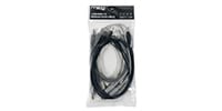 MOOG / S.M CABLE 8 6/12/18/24IN Modular patch cable
¥4,950(incl. tax)
 Back Order
 -
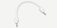 Tiptop Audio / Stackable Cable White 20cm x 5
¥5,698(incl. tax)
Back Order -
 Tiptop Audio / Stackable Cable White 30cm x 5
¥5,698(incl. tax)
Back Order -
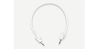
 Tiptop Audio / Stackable Cable White 50cm x 5
¥5,698(incl. tax)
Back Order -
 Tiptop Audio / Stackable Cable White 70cm x 5
¥6,050(incl. tax)
Back Order -
 Tiptop Audio / Stackable Cable White 90cm x 5
¥6,050(incl. tax)
Back Order
 KORG / MS-CABLE-YL
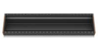 BEHRINGER / EURORACK 104
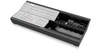 BEHRINGER / EURORACK GO
商品レビューProduct Review


不適切な投稿として報告しますか?
理由
ご協力ありがとうございました
投稿を削除しますか?
投稿されたレビューを削除しました。
Tiptop Audio
Buchla 296t Spectral Processor
Item ID:342116
116,820 yen(incl. tax)
1,168Pt(1%)Detail
- 1,168Pts
通常ポイント
- 1,168Pts
Total
- In Stock
- In Stock, can be shipped when order is confirmed.
- Low Stock
- Low Stock, may be sold out soon.
- Scheduled date
- Expected to arrive at Sound House on this date.
- TBA
- Expected date of arrival at Sound House to be determined.
- Back Order
- It needs to be orderd from the manufacturer. Please inquire about the estimated date of arrival.
- Mfr. Delivery
- Must be ordered from manufacturer. Please inquire about the estimated date of arrival.
- Download
- Only the serial number will be sent to your registered email address.
- Special Order
- Made to order item or must be ordered from manufacturer. May take several weeks or months.
- No Longer Available
- Product is no longer available due to having been discoutined or other reasons.
Rating
この商品に関連するセレクションRelated Articles

-
 Discount Sale
-
 Outlet
-
 New Arrivals
-
 Podcast (streaming)
-
 Headphones / Earphones
-
 Microphones
-
 Wireless Equipment
-
 Speakers
-
 Power Amps
-
 Mixers
-
 Processors
-
 Portable PA Systems
-
 Recorders
-
 Karaoke
-
 Guitars
-
 Basses
-
 Ukuleles
-
 Drums & Percussion
-
 Pianos / Synthesizers
-
 Wind Instruments
-
 Stringed Instruments
-
 Japanese Instruments
-
 Harmonicas, Other
-
 Software
-
 DJ & VJ
-
 Stands
-
 Cables & Connectors
-
 Racks & Cases
-
 Lighting
-
 Stage & Truss
-
 Video Equipment
-
 Computer Accessories
-
 Power Supplies
-
 Studio Furniture
-
 Household Items, Other
-
 Alcoholic Beverages
Search by Brand
Brand List


- Sound House
- 〒286-0825 14-3 Shinizumi , Narita City, Chiba
- Monday-Friday 10:00-17:00
- Narita Call Center
- TEL. 0476-89-1111
- FAX. 0476-89-2222
- Tokushima Call Center
- TEL. 0885-38-1111
- FAX. 0885-38-1100
- Showroom Hours
- Monday-Friday 10:00-17:00
closed on Saturdays, Sundays and Holidays
© Sound House

すべてのレビューを見る