


![]()
- Pianos / Synthesizers
- SYNTHESIZER
- Modular synths / sound modules
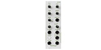
- Tiptop Audio/Buchla 245t Sequential Voltage
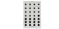
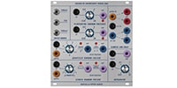
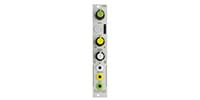
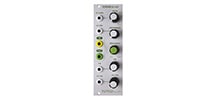
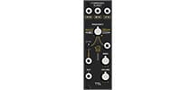
Tiptop Audio / Buchla 245t Sequential Voltage


Variations
Back Order
BD808 Bass

Back Order
CB808 Cowbell
Back Order
HATS808 Hi-Hats
Back Order
MA808 Maracas
RS808 Rimshot
Back Order
SD808 Snare
Back Order
BD909 Bass

Back Order
CP909 Clap
Back Order
CYMBL909 Cymbals
Back Order
HATS909 HI-Hats
Back Order
RS909 Rimshot
Back Order
SD909 Snare
Back Order
909-TOMS
Back Order
Sequential Voltage
Back Order
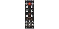
Dual Voltage Processor
Back Order
Dual Oscillator
Back Order
Source of Uncertainty
Back Order
Quad Function
Back Order
Quad Lopass Gate
Back Order
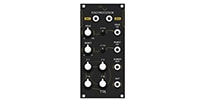
Spectral Processor

Back Order
Blind Panel 2 Set
Back Order
Circadian Rhythms
Back Order
Forbidden Planet
Back Order
MISO

Back Order
Mix7
Back Order
Mixz
ONE
ONE x 4 4台セット
QuantiZer

Back Order
VCA
Back Order
Wayout8
Back Order
Z-2040 Prophet 5 VCF
Back Order
Z-4000 NS VC-EG
Back Order
Z-8000 Matrix Sequencer

Back Order
Zeus Access

Back Order
Zeus Access Dual
Back Order
Zverb White
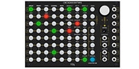
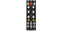
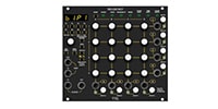
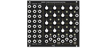
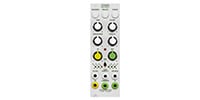


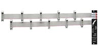
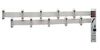
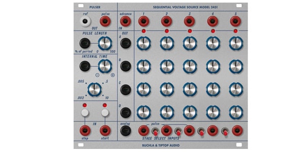
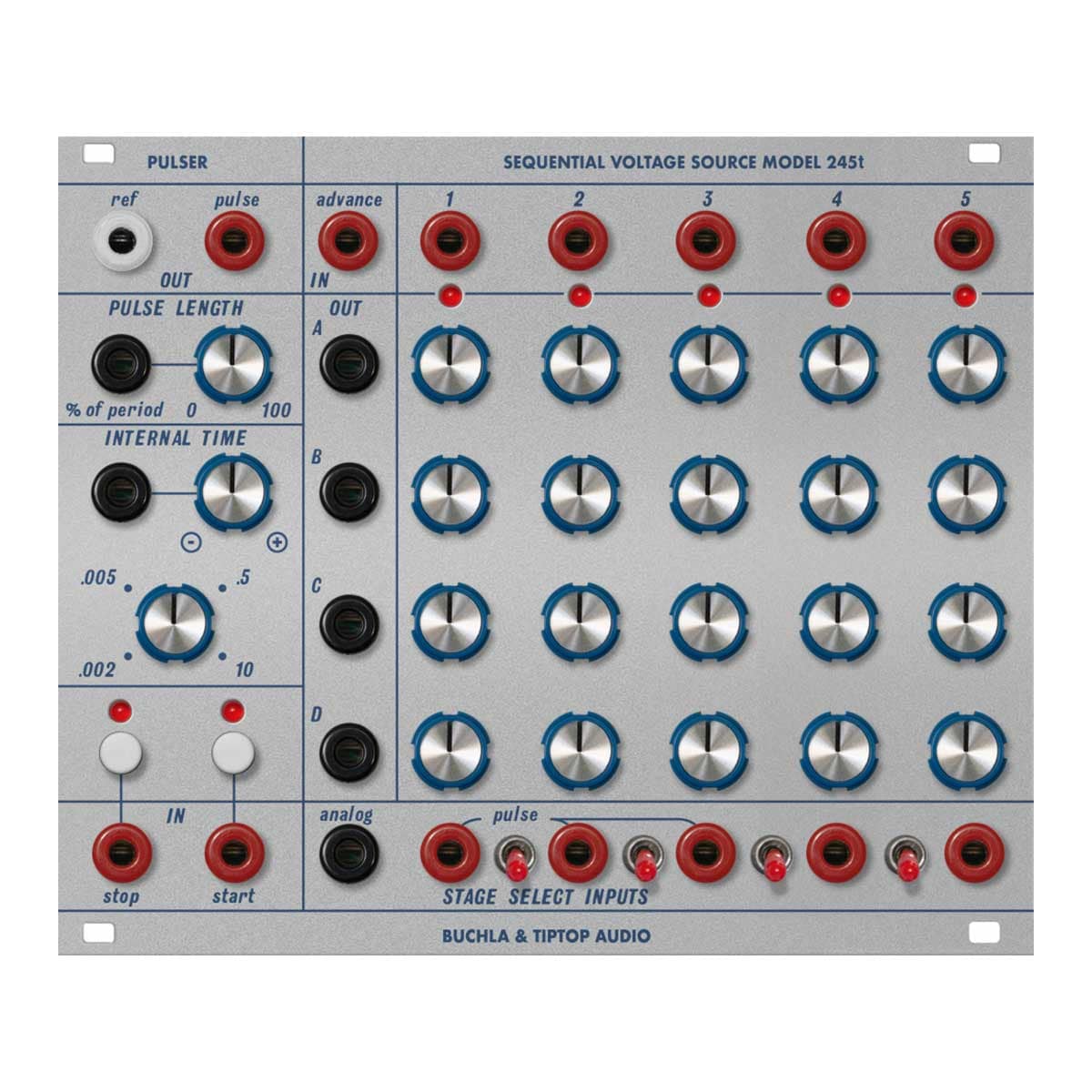
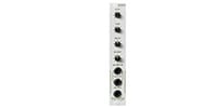
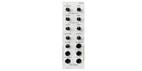
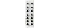
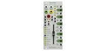
■Pulser section
The basic operation is to output two clock signals to advance the stage of the voltage stage section to the next stage. The [Pulse (Output)] terminal outputs a pulse signal.
This pulse signal starts with a 10V/100μSec pulse, followed by a 5V pulse (gate). The pulse width is variable between 0-100% duty ratio and is determined by adding the control of the external CV to the setting of the [Pulse Length] knob.
The pulse period can be set from a few milliseconds to about 10 seconds by turning the [.002-10] knob. In addition, the period of the pulse signal can be changed by adjusting the polarity and level of the external CV with the [? - ?] attenuverter knob.
The [Ref (Output)] terminal outputs a descending sawtooth signal (descending from 10V to 0V) with the same frequency as the pulse signal.
Pressing the [Start] button outputs two signals, and pressing the [Stop] button stops it. You can also input a pulse signal to each input terminal.
When the pulser is stopped, pressing the [Stop] button again will output only one pulse.
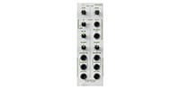
■Voltage stage section
The basic operation is a 4-track x 5-stage (step) analog sequencer, and also functions as 4 CV memories.
The output is a gate signal (10V) and a CV (0-10V) that can be set with 20 knobs. When an active stage is activated, it outputs one gate signal and four CVs simultaneously. Therefore, it can be used as a (1+4) track x 5-stage sequencer, a CV memory that can save and output up to five patterns of the four CVs you have set, and a CV preset.
You can set the number of stages that will be activated by switching each switch in [Stage Select Inputs]. In addition, inputting a pulse signal to each terminal in [Stage Select Inputs] next to the switch will instantly activate the corresponding stage.
You can select any stage by inputting CV (0-10V) to the [Analog (Input)] terminal. The voltage range is approximately Off (0V-0.75V), Stage1 (0.75V-2.5V), Stage2 (2.5V-4.25V), Stage3 (4.25V-6V), Stage4 (6V-7.75V), and Stage5 (7.75V-10V).
Normally, the signal from the Pulser section is input to the [Advance (Input)] terminal of the Voltage Stage section to advance the sequence, but
you can input a descending sawtooth wave signal to the [Analog (Input)] terminal to move the sequence backward.
If you input the CV output of one track to the [? - ? (Input)] terminal of the internal time and adjust it with the knob, you can add effects such as syncopation and shuffle to the sequence instead of equal intervals.
You can create complex sequence patterns by inputting any gate signal (10V) to any of the [Stage Select Inputs] terminals.
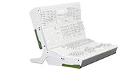
[About the Buchla & Tiptop Audio ""Eurorack 200 Series""]
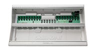
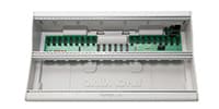
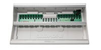
The ""Eurorack 200"" series was born from a collaboration between Tiptop Audio and the legendary West Coast synthesizer manufacturer ""Buchla"". The ""200 Series"", a very rare modular synthesizer developed about half a century ago, has been reproduced in Eurorack format. The Buchla module, the essence of West Coast style synthesis, is now available to many modern modular players. The Eurorack 200 Series will bring a West Coast feel to your modular system.
Width: 30HP
Depth: 25mm
Current consumption:
+12V: 63mA
-12V: 28mA
関連商品
-
¥800(incl. tax)
 In Stock
 -
¥10,800(incl. tax)
In Stock -
¥34,800(incl. tax)
In Stock -
 KORG / SQ-CABLE-6 PATCH CABLE for SQ-1 ミニパッチケーブル
¥1,770(incl. tax)
In Stock -
 MOOG / S.M CABLE 8 6/12/18/24IN Modular patch cable
¥4,950(incl. tax)
 Back Order
 -
 Tiptop Audio / Stackable Cable White 20cm x 5
¥5,698(incl. tax)
Back Order -
 Tiptop Audio / Stackable Cable White 30cm x 5
¥5,698(incl. tax)
Back Order -
 Tiptop Audio / Stackable Cable White 50cm x 5
¥5,698(incl. tax)
Back Order -
 Tiptop Audio / Stackable Cable White 70cm x 5
¥6,050(incl. tax)
Back Order -
 Tiptop Audio / Stackable Cable White 90cm x 5
¥6,050(incl. tax)
Back Order
 KORG / MS-CABLE-YL
 BEHRINGER / EURORACK 104
 BEHRINGER / EURORACK GO
商品レビューProduct Review


不適切な投稿として報告しますか?
理由
ご協力ありがとうございました
投稿を削除しますか?
投稿されたレビューを削除しました。
Tiptop Audio
Buchla 245t Sequential Voltage
Item ID:317687
41,470 yen(incl. tax)
414Pt(1%)Detail
- 414Pts
通常ポイント
- 414Pts
Total
- In Stock
- In Stock, can be shipped when order is confirmed.
- Low Stock
- Low Stock, may be sold out soon.
- Scheduled date
- Expected to arrive at Sound House on this date.
- TBA
- Expected date of arrival at Sound House to be determined.
- Back Order
- It needs to be orderd from the manufacturer. Please inquire about the estimated date of arrival.
- Mfr. Delivery
- Must be ordered from manufacturer. Please inquire about the estimated date of arrival.
- Download
- Only the serial number will be sent to your registered email address.
- Special Order
- Made to order item or must be ordered from manufacturer. May take several weeks or months.
- No Longer Available
- Product is no longer available due to having been discoutined or other reasons.
Rating

この商品に関連するセレクションRelated Articles

-
 Discount Sale
-
 Outlet
-
 New Arrivals
-
 Podcast (streaming)
-
 Headphones / Earphones
-
 Microphones
-
 Wireless Equipment
-
 Speakers
-
 Power Amps
-
 Mixers
-
 Processors
-
 Portable PA Systems
-
 Recorders
-
 Karaoke
-
 Guitars
-
 Basses
-
 Ukuleles
-
 Drums & Percussion
-
 Pianos / Synthesizers
-
 Wind Instruments
-
 Stringed Instruments
-
 Japanese Instruments
-
 Harmonicas, Other
-
 Software
-
 DJ & VJ
-
 Stands
-
 Cables & Connectors
-
 Racks & Cases
-
 Lighting
-
 Stage & Truss
-
 Video Equipment
-
 PC PERIPHERALS
-
 Power Supplies
-
 Studio Furniture
-
 Household Items, Other
-
 Alcoholic Beverages
Search by Brand
Brand List


- Sound House
- 〒286-0825 14-3 Shinizumi , Narita City, Chiba
- Monday-Friday 10:00-17:00
- Narita Call Center
- TEL. 0476-89-1111
- FAX. 0476-89-2222
- Tokushima Call Center
- TEL. 0885-38-1111
- FAX. 0885-38-1100
- Showroom Hours
- Monday-Friday 10:00-17:00
closed on Saturdays, Sundays and Holidays
© Sound House

すべてのレビューを見る